
Video processing apparatus

Inactive Publication Date: 2006-10-19
HITACHI LTD
View PDF2 Cites 20 Cited by
  • Summary
  • Abstract
  • Description
  • Claims
  • Application Information

AI Technical Summary

Benefits of technology

[0007] This invention was made to avoid the problems in the prior art, and it is an object of the invention to provide a video processing apparatus capable of permitting users to effectively grasp the contents of video data.
[0009] According to the invention, it becomes possible to effectively catch the contents of the video data, thereby improving the usability of end users.

Problems solved by technology

Although several techniques for allowing the user to grasp the contents of video data in a short time period are proposed, it seems that the proposed techniques fail to provide user interfaces preferable to end users.
Unfortunately, it suffers from a problem as to the lack of an ability to partially or entirely watch important video data parts within a time period convenient to the user, because it is impossible to assign a playback time and playback percentage.
Regarding the technique taught from DeMenthon document, it is difficult or almost impossible for the user to figure out exactly how to determine an appropriate scene skip ratio in order to achieve effective viewing of highlight scenes only, although an ability is provided to play back only important scenes at a ratio which is manually assigned by the user.

Method used


Image

  • Video processing apparatus
  • Video processing apparatus
  • Video processing apparatus

Examples


embodiment 1

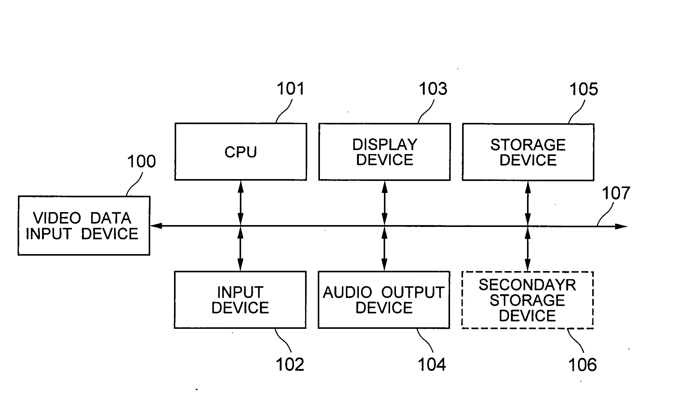
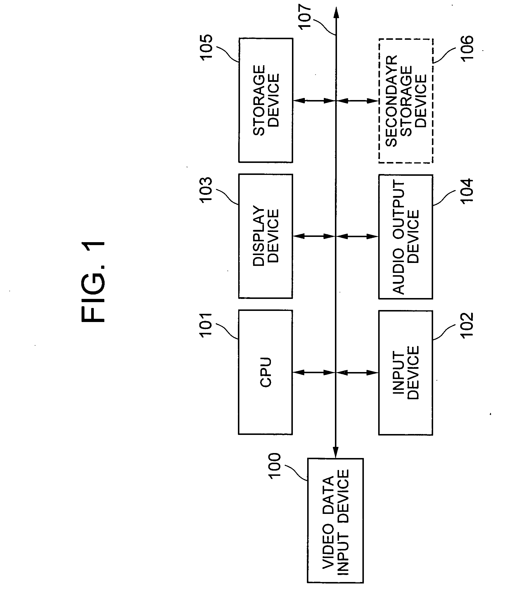
[0027]FIG. 1 shows an exemplary hardware configuration of a video processing apparatus incorporating the principles of this invention.

[0028] As shown in FIG. 1, the video processing apparatus in accordance with the embodiment 1 is generally made up of a video data input device 100, a central processing unit (CPU) 101, an input device 102, a display device 103, an audio output device 104, a storage device 105, and a secondary storage device 106. Respective devices are connected together by a bus 107 to thereby permit mutual data transfer / reception therebetween. Note here that the secondary storage device 106 is an auxiliary component of the storage device 105 and thus is eliminatable in cases where the storage device 105 has extended functionality covering the function of it.

[0029] The video data input device 100 inputs video or video data. This input device 100 may typically be comprised of a device which reads the video data being stored in the memory device 105 or secondary stor...

embodiment 2

[0106] In an embodiment 2, a video processing apparatus is provided, which performs ranking (grading) of scenes in the video or video data and then determines based thereon appropriate highlight scenes and playback scenes.

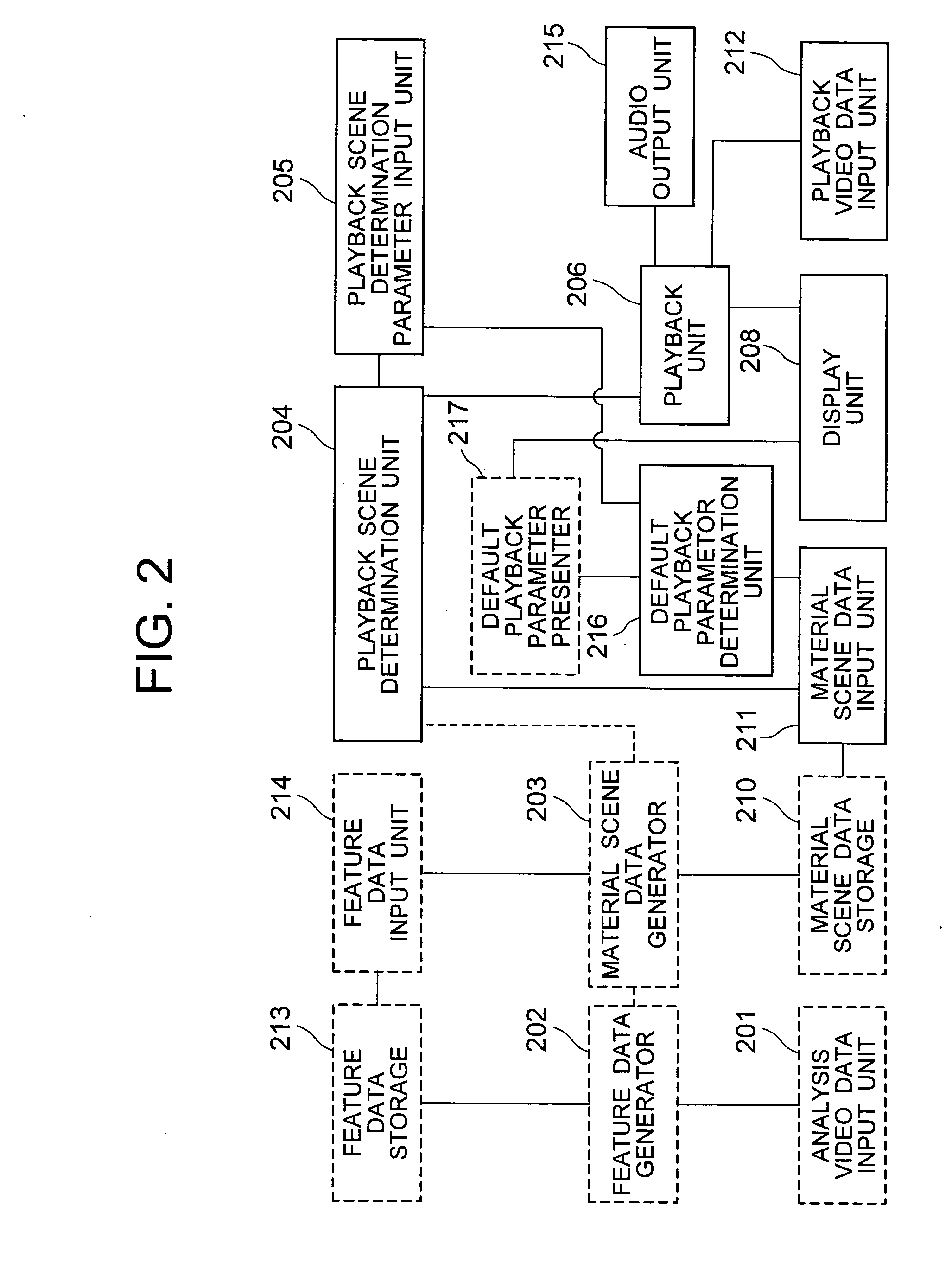
[0107]FIG. 11 is a functional block diagram of the video processing apparatus in accordance with the embodiment 2.

[0108] As shown in FIG. 11, the video processing apparatus of this embodiment is made up of a ranking data generation unit 1501 and a ranking data retaining unit 1502 plus a ranking data input unit 1503 in addition to the function blocks of the video processing apparatus of the embodiment 1 stated supra. While these function blocks may be partly or entirely realized in the form of hardware in addition to the hardware configuration shown in FIG. 1, such are alternatively realizable by software programs executable by the CPU 101. In the description below, it is assumed that all of these function blocks are software programs to be executed by CPU 101, as...


PUM


Abstract

A video processing technique which enables users to effectively watch highlight scenes while listening to audio part thereof in a short period of time is disclosed. Upon input of video data, highlight scene data describing therein a highlight scene(s) in the video data is input or generated. Then, based this highlight scene data, determine a default playback parameter. Control is provided to reproduce the highlight scene(s) of the video data in a way such that when inputting a parameter for determination of a playback scene(s), this input playback parameter is used while giving thereto higher priority than the default playback parameter.

Description

INCORPORATION BY REFERENCE [0001] The present application claims priority from Japanese application JP2005-120484 filed on Apr. 19, 2005, the content of which is hereby incorporated by reference into this application. BACKGROUND OF THE INVENTION [0002] The present invention relates to an apparatus for processing moving pictures to reproduce video data. [0003] Recent advances in digital television broadcast technologies bring rapid growth in multi-channel broadcasting of video or video data and also result in wider frequency bands of networks. This in turn enabled acquisition or audio-visual enjoyment of a great amount of video data. In addition, owing to improvements in video compression / decompression techniques and price reduction of hardware / software for achieving them along with an increase in capacity of storage media and a decrease in costs thereof, it has become possible to readily perform the saving of an increased amount of video data, which leads to a likewise increase in w...

Claims


Application Information

Patent Timeline
IPC IPC(8): H04N7/00G11B20/10G11B27/00G11B27/02H04N5/93
CPCH04N5/783H04N5/9201H04N21/4325H04N21/8456H04N21/458H04N21/84H04N21/4532
Inventor HIROI, KAZUSHIGEFUJIKAWA, YOSHIFUMISASAKI, NORIKAZUUEDA, RIRIHAYASHI, AKIOFUJII, YUKIOKAWAGUCHI, ATSUO
Owner HITACHI LTD
Learn More