
Belt drive system with outer rotor motor

a belt drive and outer rotor technology, applied in the direction of dynamo-electric converter control, dynamo-electric gear control, magnetic circuit shape/form/construction, etc., can solve the problems of unfavorable heat removal, unfavorable motor torque output, and difficulty in reducing the torque output of the motor, so as to achieve effective motor cooling, reduce the ripple and smooth effect of torque and improve the effect of efficiency

Inactive Publication Date: 2006-10-19
AEC MOTIONSTAR
View PDF19 Cites 41 Cited by
  • Summary
  • Abstract
  • Description
  • Claims
  • Application Information

AI Technical Summary

Benefits of technology

"The present invention is directed to improving belt driving systems, particularly in treadmills, by using a brushless permanent magnet outer-rotor motor, a roller, an endless belt, and a motor controller. The invention addresses three major issues: motor smoothness at low speeds, motor response to load disturbance such as step fall, and motor surface temperature. The invention provides an improved cooling method for the outer rotor motor, which allows for smaller size and higher power density, and ensures that the motor surface temperature stays lower to increase the life of the belt. The invention also uses an advanced field orientation control algorithm for the motor controller to achieve fast speed response and accurate speed control. Additionally, the invention includes a high resolution speed and position sensor for accurate motor rotor position and speed feedback information. Overall, the invention provides a more reliable and smooth belt drive system for treadmills and other applications."

Problems solved by technology

However, challenges remain, especially in thermal cooling for motor surface temperature, motor smoothness at low speed, and motor response to load such as a step-fall on a treadmill belt.
This represents undesired motor torque output.
For an outer rotor motor, the stator is inside the rotor housing so heat removal is difficult.
However, this approach may not be entirely effective to remove heat from inside the motor housing.
For example, end caps having ventilation holes may not be effective at removing the heat when the motor is running at lower speed, and by having ventilation holes at both end caps, foreign objects may be sucked in and cause hazards.
The motor described in U.S. Pat. No. 6,455,960 relies on the supporting structure for conductive heat dissipation which strategy may become less effective as the motor shaft becomes longer in applications such as treadmills.
Also, in certain cases there may not be enough supporting structure available for conductive heat dissipation.
In addition, the contact area of the shaft with the supporting frame may be limited, further reducing the effects of conductive heat transfer.
As a result, at full load and lower speed, both methods cited above may have difficulties keeping the rotor surface temperature low.
Higher rotor surface temperatures can have adverse effects on the life of the belt, and can make an outer rotor motor unsuitable for certain applications.

Method used


Image

  • Belt drive system with outer rotor motor
  • Belt drive system with outer rotor motor
  • Belt drive system with outer rotor motor

Examples


Embodiment Construction

[0034] It will be readily understood that the components and methods of cooling, smoothness and fast response of the present invention, as generally described and illustrated in the figures herein, can be designed in a wide variety of different configurations and combinations depending on the specific application for a motor. Thus, the following more detailed description of the embodiments of the system and methods of the present invention, as represented in FIGS. 1-16, is not intended to limit the scope of the invention, as claimed, but is merely representative of the presently preferred embodiments of the invention.

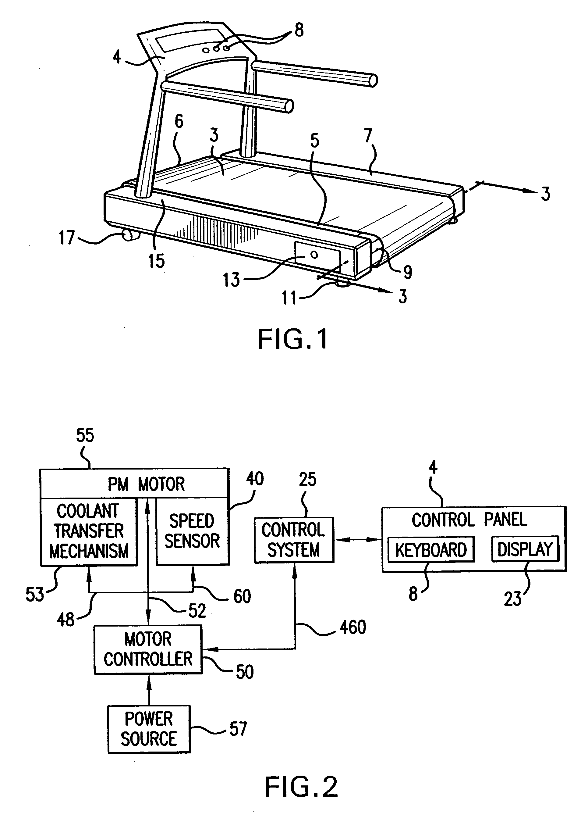
[0035] In FIG. 1 a belt driving system configured as a treadmill is shown and includes a control panel 4 secured to a frame structure 7, 15 and operably connected to the control system 25 (FIG. 2) and wherein the control panel 4 includes at least a set of user controls 8 effective to permit a user to control the speed of a belt 3. The belt driving system comprises a di...


PUM


Abstract

An outer rotor motor comprises a tubular shaft for maximum motor cooling effect. Coolant may flow through coolant channels of the shaft and the motor in various configurations to carry away the heat. A thermally conductive component may be inserted into the hollow shaft under the stator section to optimize the airflow and cooling. Physical construction of the motor and control algorithms may further enhance motor performance with appropriate sensors. A compact, smooth, and cool operating motor may thus be achieved for applications such as treadmills or other belt drive systems.

Description

BACKGROUND OF THE INVENTION [0001] 1. Field of the Invention [0002] The present invention is related to improvements for outer-rotor electric motor systems, particularly where the outer rotor is used to directly drive a belt, such as in treadmills and conveyors. [0003] 2. Discussion of the Related Art [0004] Outer rotor motors are gaining popularity in many different commercial and residential applications since a direct-drive motor can simplify the overall system structure, increase system reliability and reduce system cost. Traditional treadmills and conveyors have a roller that is driven by conventional AC or DC electric motor through belts and pulleys. In addition, the AC or DC motor normally has a flywheel attached to achieve a smooth speed performance, such as in treadmill applications. [0005] A typical outer roller motor has a rotating roller supported by end caps and bearings, and a stator and shaft. Permanent magnets are mounted cylindrically inside the roller and form magn...

Claims


Application Information

Patent Timeline
Patent Type & Authority Applications(United States)
IPC IPC(8): H02K9/00H02K11/00H02K23/66A63B22/02A63B24/00H02K5/00H02K5/22H02K7/08H02K7/10H02K9/06H02PH02P21/00
CPCA63B22/02A63B22/0235A63B22/0242A63B2022/025A63B2220/34A63B2225/30H02K11/0073H02K5/225H02K7/088H02K7/1016H02K9/06H02K11/0031H02K5/00H02K2211/03A63B22/025H02K11/225H02K11/33
Inventor CHENG, WEI
Owner AEC MOTIONSTAR
Learn More