
Variable wavelength optical filter

Inactive Publication Date: 2006-10-12
NIPPON TELEGRAPH & TELEPHONE CORP
View PDF1 Cites 26 Cited by
  • Summary
  • Abstract
  • Description
  • Claims
  • Application Information

AI Technical Summary

Benefits of technology

[0034] Moreover, according to a wavelength tunable optical filter of the present invention, by using two or more Fabry-Perot etalon type filters having a respectively different FSR, a voltage to be applied per unit thickness of the crystal is reduced and therefore an operation under moderate conditions is realized.
[0035] Furthermore, according to the present invention, by reducing an area of the electrode, capacitance of the filter can be reduced. In addition, by using metal having a low volume resistivity for the electrode, an operation at an order of 10 nsec can be realized.

Problems solved by technology

For this reason, the above technologies have a drawback in that they cannot realize an operating speed of 1 to 10 nsec required to perform an add / drop of an optical packet that is required in a next generation optical network.
Since the electric field is not feasible, a material exerting a larger electro-optic effect has been expected.

Method used


Image

  • Variable wavelength optical filter
  • Variable wavelength optical filter
  • Variable wavelength optical filter

Examples


first embodiment

A First Embodiment

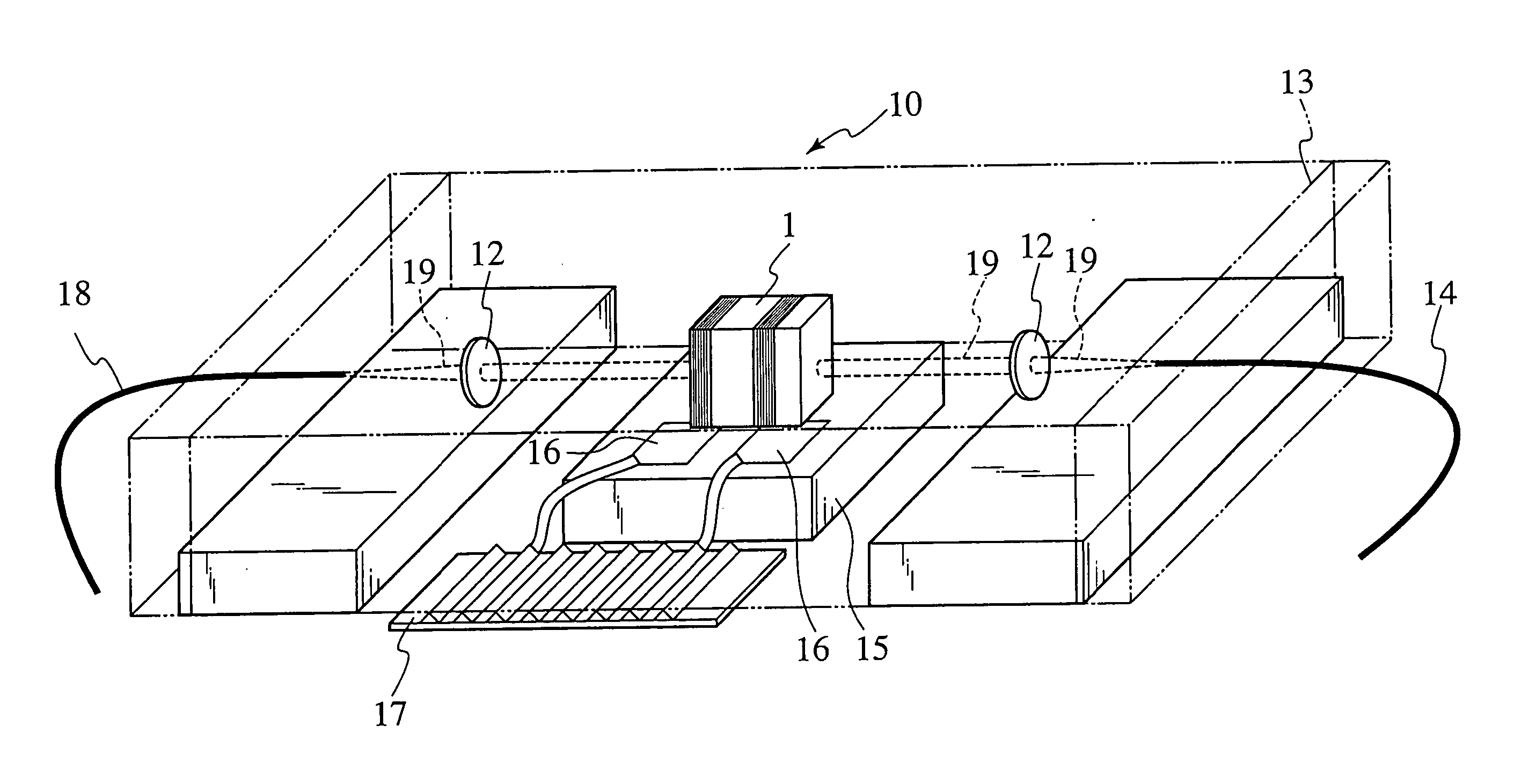
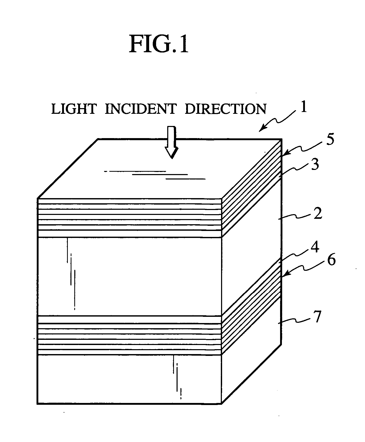
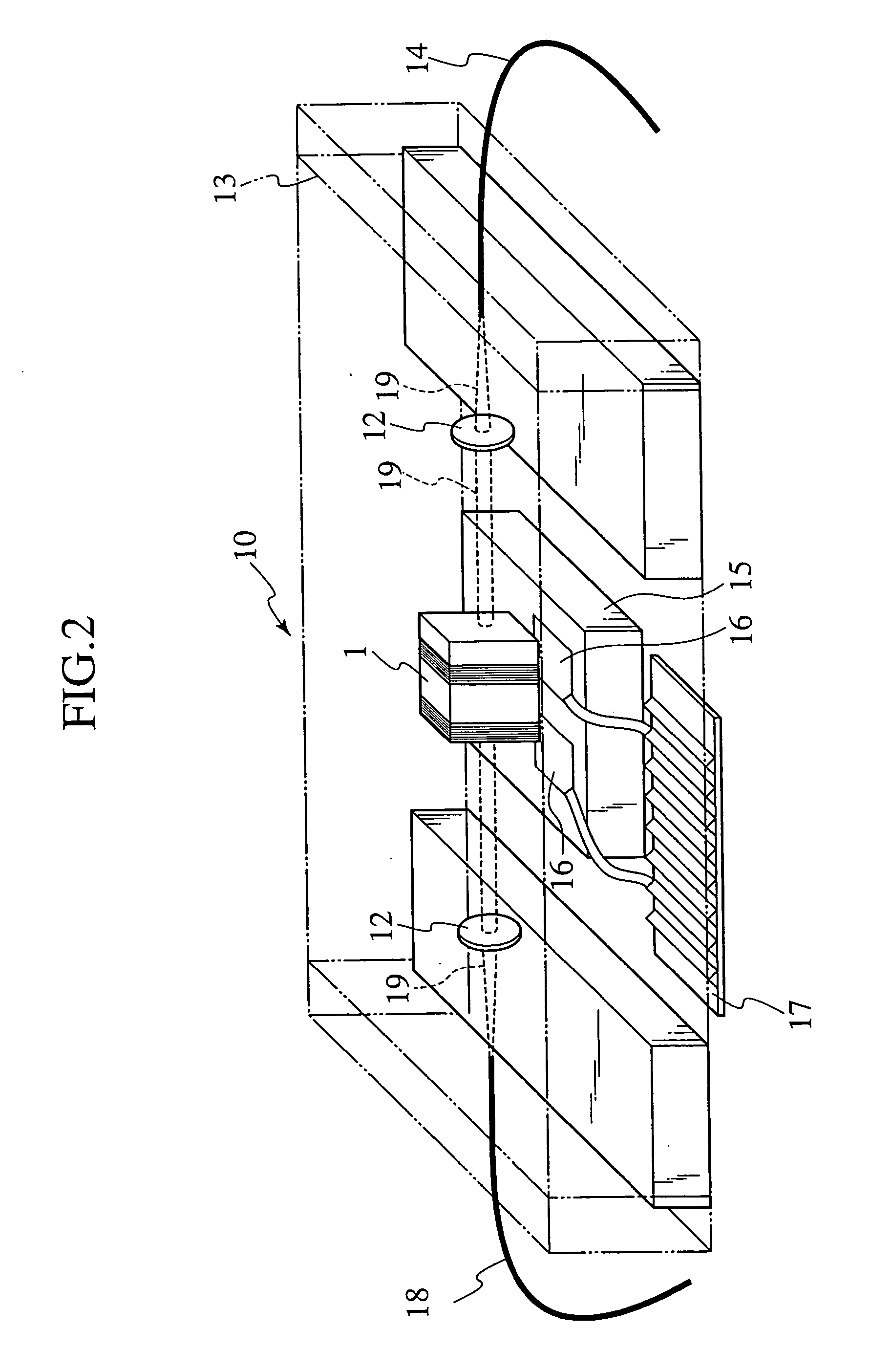
[0087]FIG. 1 illustrates a schematic diagram of a wavelength tunable optical filter according to a first embodiment.

[0088] A dielectric crystal portion 2 of a wavelength tunable optical filter 1 according to this embodiment is formed of a KLTN crystal. Adjustment of the composition ratio of Li and Nb can change a phase transition temperature.

[0089] A composition of the KLTN crystal that forms the dielectric crystal portion 2 is K0.97Li0.03Ta0.65Nb0.35O3, and its phase transition temperature was 19 degrees Celsius. Although Li composition is 0.03 in this embodiment, the second-order phase transition is obtained also for the composition of 0.001 and at a Li composition ratio of up to 0.1, the crystal can maintain a cubic system. Therefore, when a Li composition is kept in such a range, a practically suitable optical filter is obtained. Particularly, in a Li composition of 0.01-0.06, a high quality crystal is obtained and therefore high relative electric permittivit...

second embodiment

A Second Embodiment

[0109] A second embodiment exemplifies a wavelength tunable optical filter similar to that in the first embodiment, except in that the wavelength tunable optical filter concerned has two Fabry-Perot etalon type filters.

[0110] Referring to FIG. 8, a wavelength tunable optical filter 26 is constructed by stacking a dielectric multilayer mirror 31, a transparent electrode 33, a dielectric crystal portion 30, a transparent electrode 34, a dielectric multilayer mirror 29, a transparent electrode 35, a dielectric crystal portion 28, a transparent electrode 36, and a multilayer mirror 29 in this order on a glass substrate 32. In other words, the wavelength tunable optical filter 26 has two dielectric crystal portions 28, 30 and four (two pairs of) electrodes. Besides, the filter 26 is practically composed of two etalon-type filters arranged in series with each other (along the direction of the light transmission) with the dielectric multilayer mirror 29 in-between. Whil...

third embodiment

A Third Embodiment

[0120] In a third embodiment, a wavelength tunable optical filter having the same FSR as the filters in the second embodiment is configured by stacking a KLTN crystal and ITO electrodes. When an FSR is 10 nm, a thickness of the KLTN crystal is about 55 micrometers, which corresponds to half the wavelength multiplied by 200. This thickness is divided by 5 and on each of them is deposited the ITO film having a thickness of half the wavelength.

[0121]FIG. 10 is a schematic view of a wavelength tunable optical filter 37 according to the third embodiment of the present invention. As shown in FIG. 10, a multilayer body is formed on a glass substrate 42, the body having three transparent electrodes 40 (positive), three transparent electrodes 43 (negative), and five dielectric crystal portions 38 and being sandwiched by dielectric multilayer mirrors 39, 41.

[0122] In addition, a voltage is applied across the transparent electrodes 40, 43 so that each transparent electrode ...


PUM


Abstract

A wavelength tunable optical filter (1) comprises a dielectric crystal portion (2) comprised of a dielectric crystal having a cubic system and exhibiting a quadratic electro-optic effect, a mirror portion (5, 6) constituting a Fabry-Perot etalon in cooperation with said dielectric crystal portion, and an electrode (3, 4) configured to apply a voltage to said dielectric crystal portion thereby to change a wavelength of light transmitting through said etalon on a basis of said electro-optic effect. According to the configuration, since the dielectric crystal having a cubic system and exhibiting a quadratic electro-optic effect is used, there is provided a wavelength tunable optical filter that is capable of operating at high-speed on application of a low voltage.

Description

TECHNICAL FIELD [0001] The present invention relates to a wavelength tunable optical filter for use in optical communication, optical measurement and the like. BACKGROUND ART [0002] In addition to a realization of a high-capacity, high-speed, and sophisticated network, an optical communication has been applied to an access network, an example of which is introduction of fiber-to-the-home. In the future, a further sophistication of a communication network will be required, with an expectation of a more effective utilization of wavelengths. [0003] In a Dense Wavelength Division Multiplexing (D-WDM) system, more than two optical signals at closely spaced wavelengths are multiplexed and transmitted via a single optical wave-guide, thereby enhancing a communication capacity. In a transmitting side, more than two optical signals having different wavelengths at extremely narrow intervals of 0.8 nm from one another are multiplexed over a range of several tens nanometers, thereby enabling a ...

Claims


Application Information

Patent Timeline
IPC IPC(8): G02B6/00G02B5/28G02F1/21
CPCG02B5/288G02F2203/055G02F2001/213G02F1/21G02F1/213G01J3/26G02B6/29358
Inventor SHIMOKOZONO, MAKOTOFUJIURA, KAZUOTOYODA, SEIJIIMAI, TADAYUKI
Owner NIPPON TELEGRAPH & TELEPHONE CORP
Learn More