Holding circuit, electromagnetic valve, valve selector, and flow controller
- Summary
- Abstract
- Description
- Claims
- Application Information
AI Technical Summary
Benefits of technology
Problems solved by technology
Method used
Image
Examples
example 1
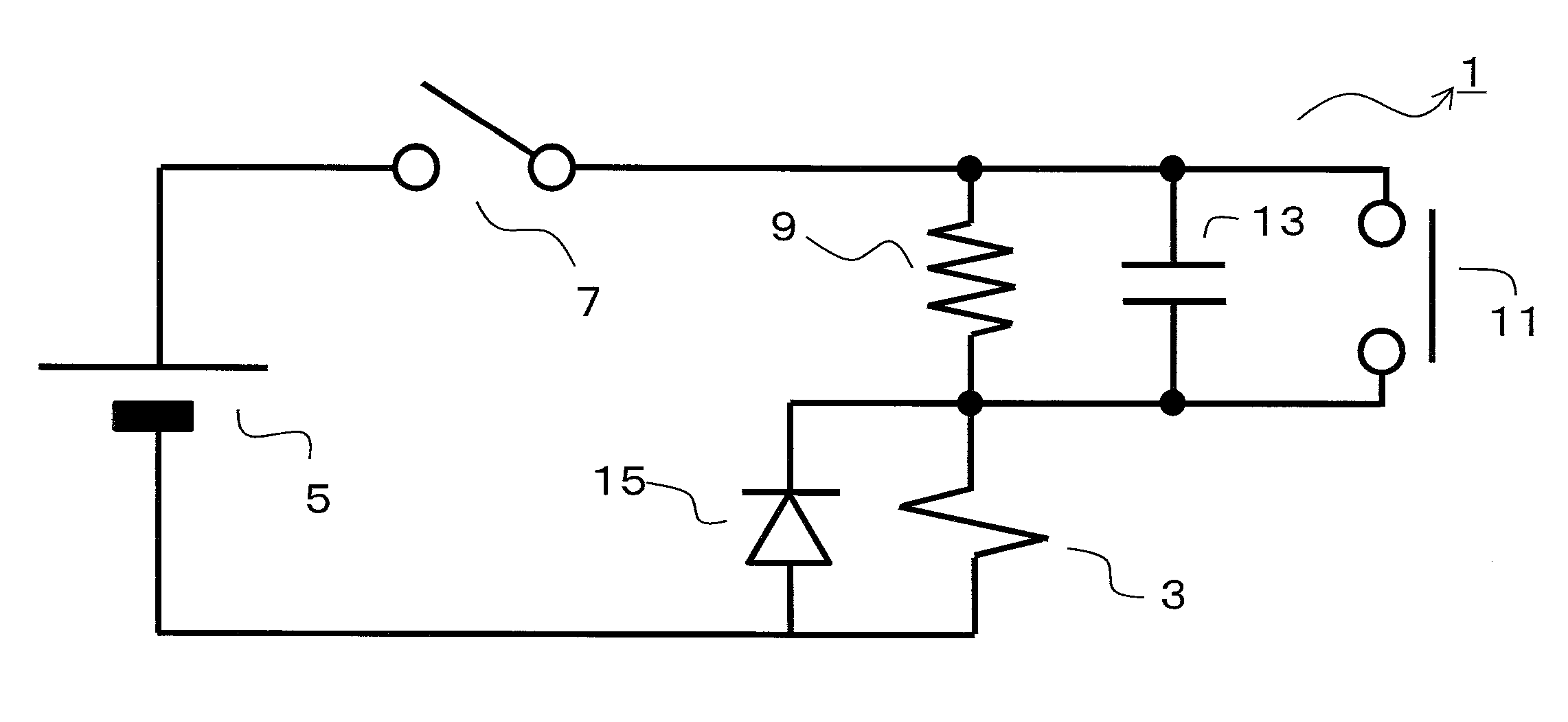
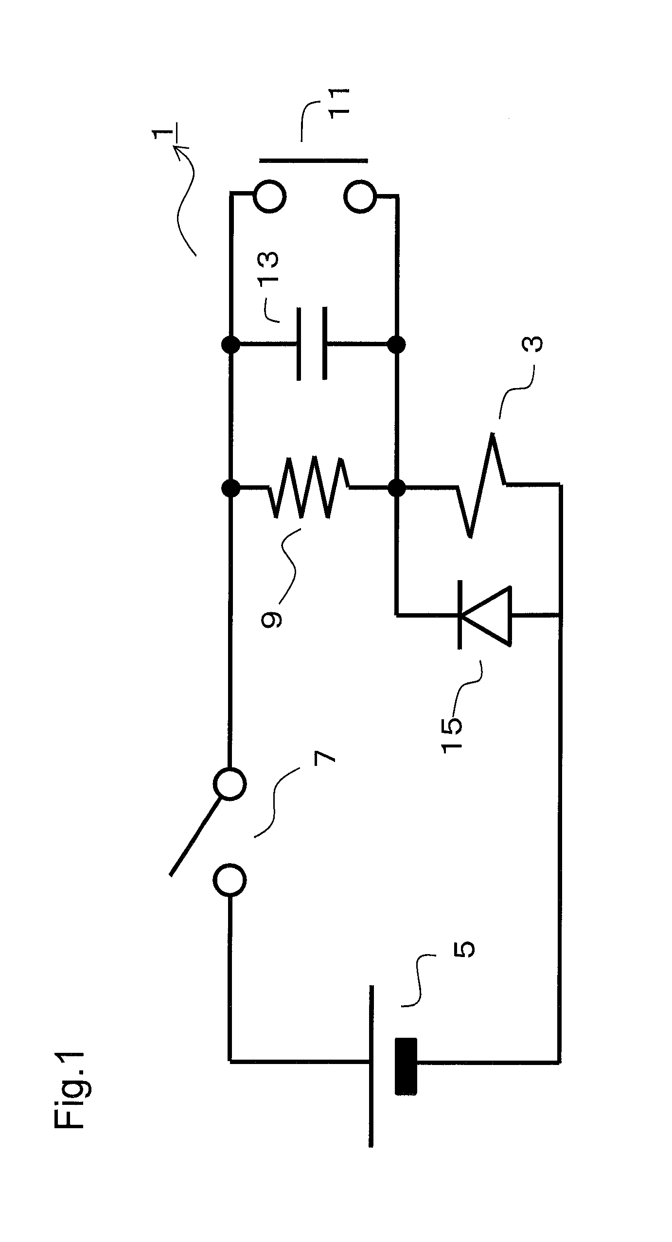
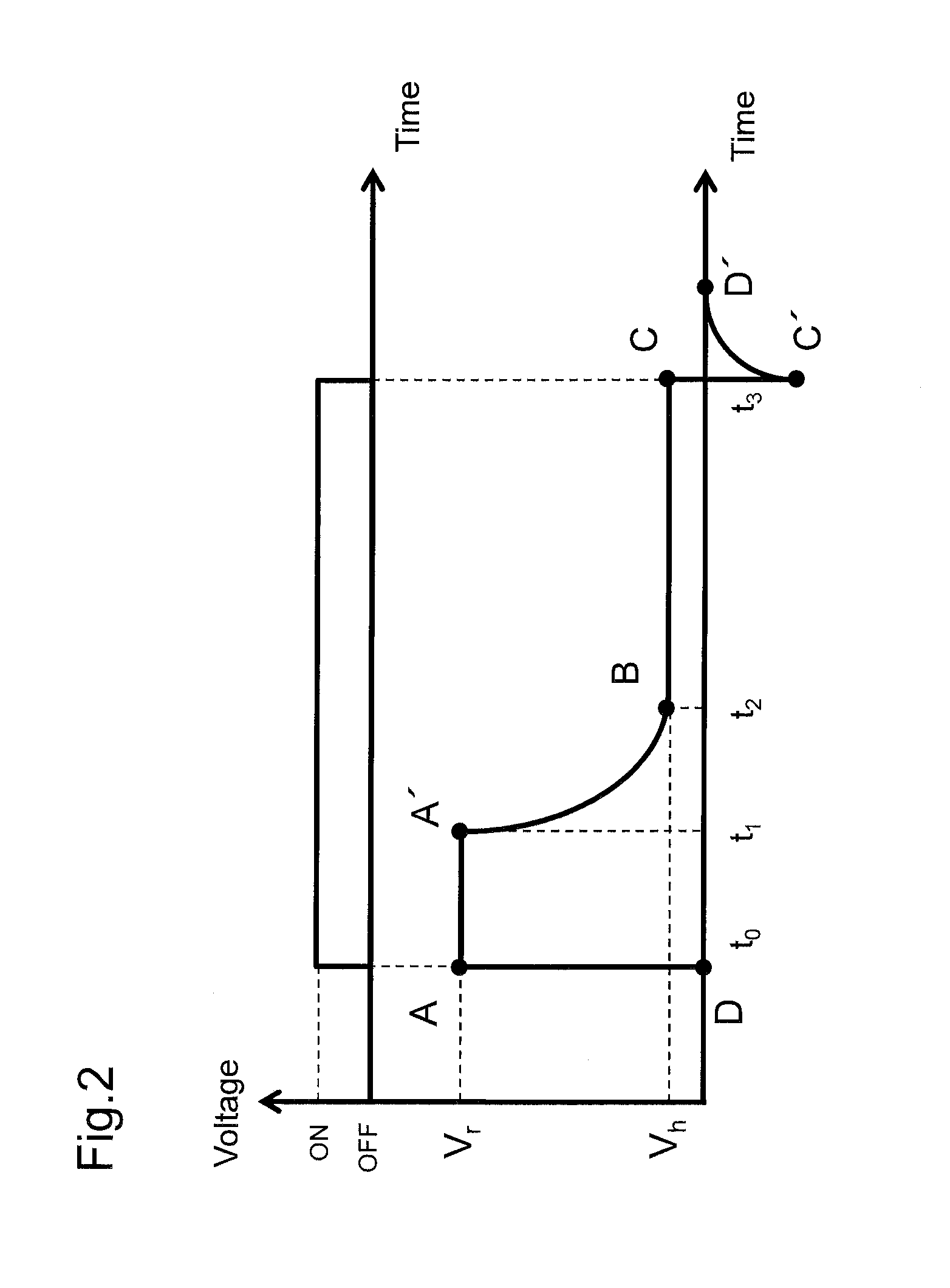
[0041]FIG. 1 shows a circuit diagram of the holding circuit 1 in accordance with an embodiment of the present invention. FIG. 2 shows a diagram which illustrates the temporal change of voltage in the holding circuit 1 of FIG. 1.
[0042]In general, a flow controller for transporting solution has a valve selector for transporting several kinds of solutions without mixing them. In the valve selector, solenoid valves are commonly used for opening or closing the gate to tubes through which the solutions flow. The solenoid 3 in the holding circuit 1 in FIG. 1 is used as a solenoid valve, for example. To the solenoid used as a solenoid valve, rated voltage is applied in order to drive the valve and holding voltage smaller than the rated voltage is applied in order to hold the switching condition of the solenoid valve. The temperature of the solenoid of 1 W power consumption increases to as high as 80 degrees Celsius after one and half a minute energization at the rated voltage. If such a sol...
example 2
[0065]Next, referring to FIGS. 4 and 5, a holding circuit in accordance with another embodiment of the present invention is described. FIG. 4 shows a circuit diagram of the holding circuit 71 in accordance with another embodiment of the present invention. FIG. 5 shows a diagram which illustrates the temporal change of voltage and current. Below, the holding circuit 71 is explained, focusing on the difference from the holding circuit 1.
[0066]The holding circuit 71 comprises a capacitor 81 (an example of “second capacitor” in Claims) in place of the second switch 11. The capacitor 81 is different from a capacitor 83 (an example of “capacitor” in Claims) corresponding to the capacitor 11. The capacitor 81 is connected in parallel with the capacitor 83. The capacity of the capacitor 81 is larger than that of the capacitor 83.
[0067]In addition, the holding circuit 71 comprises a contactor 77 (an example of “contactor” in Claims) in place of a switch corresponding to the first switch 7. T...
example 3
[0080]Next, referring to FIG. 6, a flow controller with the holding circuit 1 in FIG. 1 or the holding circuit 71 in FIG. 4 is described. FIG. 6 shows a schematic block diagram of a flow controller 31 with the holding circuit 1 in FIG. 1.
[0081]The flow controller 31 comprises a solution transport unit 33 which transports solution and a solution transport controller 35 which controls the solution transport behavior of the solution transport unit 33. The solution transport unit 33 comprises a valve selector 37 and a flow path 39. The valve selector 37 controls the inflow into the flow path 39 and the outflow out of the flow path 39 of a plurality of solutions. The valve selector 37 comprises the holding circuit 11 shown in FIG. 1 and a solenoid valve 411. The holding circuit 11 controls the solenoid valve 411 to keep the behavior of the solenoid valve at low holding voltage. Here, the holding circuit 711 may be used instead of the holding circuit 11.
[0082]The solution transport unit 3...
PUM
 Abstract
Description
Claims
Application Information
 - R&D
- Intellectual Property
- Life Sciences
- Materials
- Tech Scout
- Unparalleled Data Quality
- Higher Quality Content
- 60% Fewer Hallucinations
Browse by: Latest US Patents, China's latest patents, Technical Efficacy Thesaurus, Application Domain, Technology Topic, Popular Technical Reports.
© 2025 PatSnap. All rights reserved.Legal|Privacy policy|Modern Slavery Act Transparency Statement|Sitemap|About US| Contact US: help@patsnap.com


