Eureka AIR delivers breakthrough ideas for toughest innovation challenges, trusted by R&D personnel around the world.

Anti-flip landing gear for aircraft

a technology for landing gear and amphibious aircraft, which is applied in the direction of seaplanes, floating ships, transportation and packaging, etc., can solve the problems of increasing the number of aircraft in the air, new development, and safety issues, and achieve the effect of preventing the flipping of amphibious aircra

Active Publication Date: 2006-10-12
ICON AIRCRAFT
View PDF11 Cites 12 Cited by
  • Summary
  • Abstract
  • Description
  • Claims
  • Application Information

AI Technical Summary

Benefits of technology

[0013] In another embodiment of the present invention, a system for preventing flipping of an amphibious aircraft during water landing is disclosed. The system includes landing gear extending vertically downwards from an underside of the aircraft. The system further includes a flexible support coupled to the landing gear, wherein the flexible support allows the landing gear to flex vertically when a vertical force is applied to the landing gear. The landing gear flexes vertically when water contacts the landing gear during water landing, so as to prevent the aircraft from flipping. A force necessary to flex the flexible support in a vertical direction is less than a force necessary to flip the aircraft during water landing. In one alternative, the flexible support comprises a leaf spring.

Problems solved by technology

This new development, however, will not come without its drawbacks.
Almost as soon as the new aircraft and pilot certifications emerge, so will safety issues.
The increase in the number of aircraft in the air increases the potential for accidents during flight.
The potential for accidents is further compounded by the reduced experience required of the new pilot certification.
If this landing gear is inadvertently left deployed when the amphibious aircraft lands on the water, the aircraft can be damaged and will likely flip over and submerge.
Currently, there is no commercially available system for handling the inadvertent deployment of landing gear during water landing and preventing the resulting flipping of the amphibious aircraft.

Method used


Image

  • Anti-flip landing gear for aircraft
  • Anti-flip landing gear for aircraft
  • Anti-flip landing gear for aircraft

Examples


Embodiment Construction

[0022]FIG. 1 is an illustration of a landing gear system 100 for preventing flipping of an amphibious aircraft during water landing, in one embodiment of the present invention. The landing gear system 100 of FIG. 1 is situated along the underside of an aircraft, such as an amphibious light-sport aircraft. FIG. 1 shows vertical strut 102, which is a structural member that sustains tension or compression loads along its length axis. Vertical strut 102 attaches to the landing gear wheel 104 at its center point 106 and serves to connect the landing gear to the aircraft. Also shown is diagonal strut 108 which connects to vertical strut 102 and sustains tension or compression loads along its length axis. Diagonal strut 108 is positioned diagonally and connects the vertical strut 102 to the aircraft.

[0023] Disposed along the length of diagonal strut 108 is locking mechanism 110, which serves to lock the landing gear in place during use. In one embodiment of the present invention, the lock...


PUM


Abstract

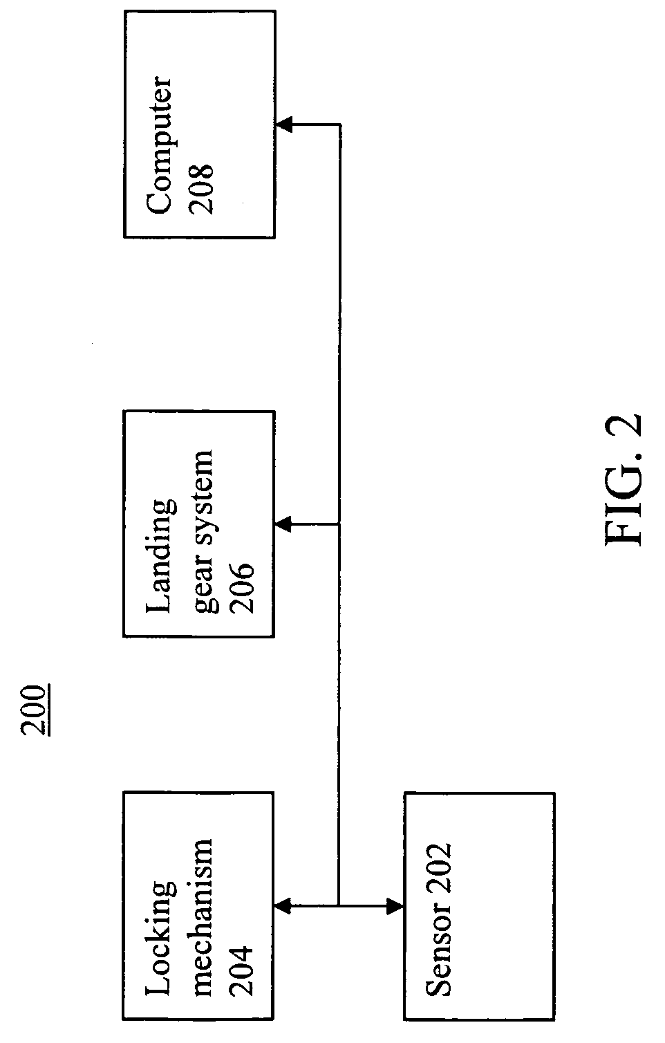
A system for controlling landing gear of an aircraft is disclosed. The apparatus includes a sensor for sensing water, wherein the sensor is coupled to the landing gear and a retracting device for retracting the landing gear when the sensor senses a body of water. In one alternative, the aircraft is an amphibious aircraft and the sensor senses electrical conductivity. In another alternative, the retracting device comprises a hydraulic system for deploying and retracting the landing gear, wherein the hydraulic system retracts the landing gear when the sensor senses a body of water. In yet another alternative, the retracting device comprises a locking mechanism that locks the landing gear to the aircraft, wherein the locking mechanism unlocks the landing gear so as to detach it from the aircraft when the sensor senses a body of water.

Description

CROSS-REFERENCE TO RELATED APPLICATIONS [0001] The present patent application claims priority to U.S. provisional patent application Ser. No. 60 / 669,762 filed on Apr. 8, 2005 and entitled “Anti-Flip Landing Gear for Amphibious Airplanes.” U.S. provisional patent application Ser. No. 60 / 669,762 is hereby incorporated by reference in its entirety.STATEMENT REGARDING FEDERALLY SPONSORED RESEARCH OR DEVELOPMENT [0002] Not Applicable. INCORPORATION BY REFERENCE OF MATERIAL SUBMITTED ON A COMPACT DISC [0003] Not Applicable. FIELD OF THE INVENTION [0004] The invention disclosed broadly relates to the field of light-sport aircraft design and more particularly relates to the field of landing gear for amphibious aircraft. BACKGROUND OF THE INVENTION [0005] The Federal Aviation Administration (FAA) recently instituted a new aircraft certification for Light-Sport Aircraft. Section 1.1 of title 14 of the Code of Federal Regulations (CFR) puts forth the details of the new certification. Light-spo...

Claims


Application Information

Patent Timeline
Patent Type & Authority Applications(United States)
IPC IPC(8): B64C25/14B64C35/00
CPCB64C25/00B64C25/10B64C35/00B64C25/66B64C25/30
Inventor HAWKINS, THOMAS
Owner ICON AIRCRAFT
Why Eureka
Eureka Blog
Learn More