
Heat sink apparatus for electronic device

a technology for electronic devices and heat sinks, applied in lighting and heating apparatus, electrical devices, cooling/ventilation/heating modifications, etc., can solve problems such as malfunctions or even affect nearby devices, electrical devices are especially sensitive to heat, and heat sinks cannot be used in compact systems or slim systems

Inactive Publication Date: 2006-10-12
SAMSUNG ELECTRONICS CO LTD
View PDF5 Cites 107 Cited by
  • Summary
  • Abstract
  • Description
  • Claims
  • Application Information

AI Technical Summary

Problems solved by technology

Electronic devices are especially sensitive to heat among other environmental factors.
Thus, if electronic devices are over heated, they can malfunction or even affect nearby devices.
Consequently, the heat sink cannot be used in a compact system or a slim system.
However, the microchannels and the manifold layer are directly connected to each other, which increases the thickness of the heat sink.
Therefore, the microchannel heat sink assembly cannot not be used in slim electronic devices.

Method used


Image

  • Heat sink apparatus for electronic device
  • Heat sink apparatus for electronic device
  • Heat sink apparatus for electronic device

Examples


Embodiment Construction

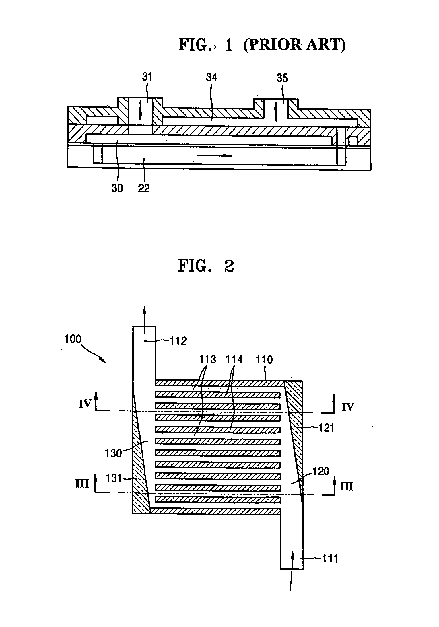
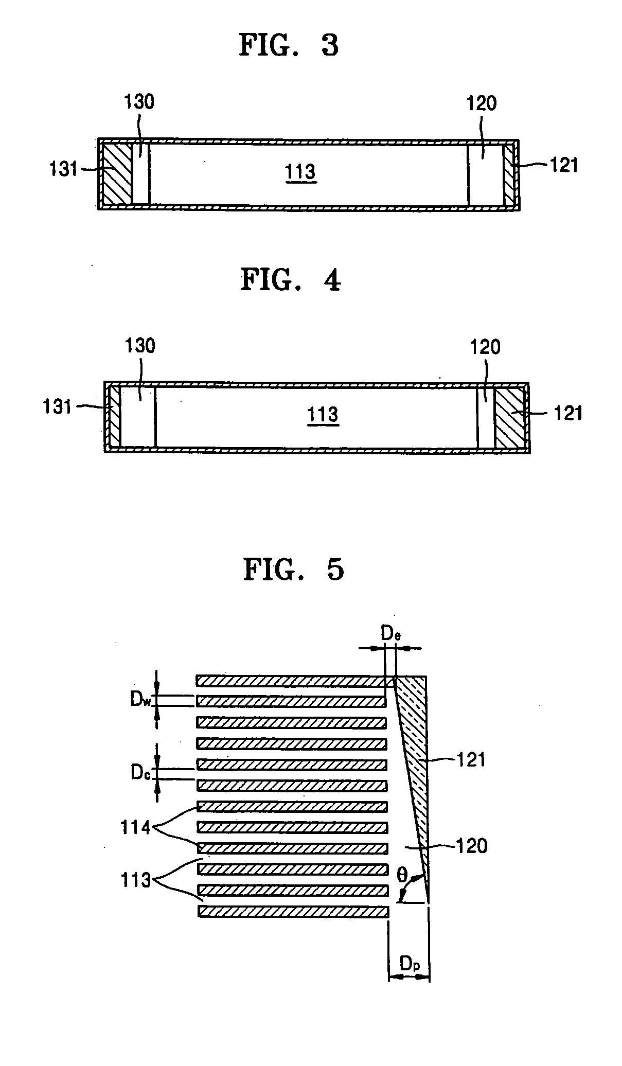
[0031]FIG. 2 is an elevational view in cross section of a heat sink apparatus 100 for an electronic device (not shown) according to a first exemplary embodiment of the present invention. FIG. 3 is an elevational view in cross-section of the heat sink apparatus 100 taken along the line III-III′ in FIG. 2. FIG. 4 is an elevational view in cross-section of the heat sink apparatus 100 taken along the line IV-IV′ in FIG. 2.

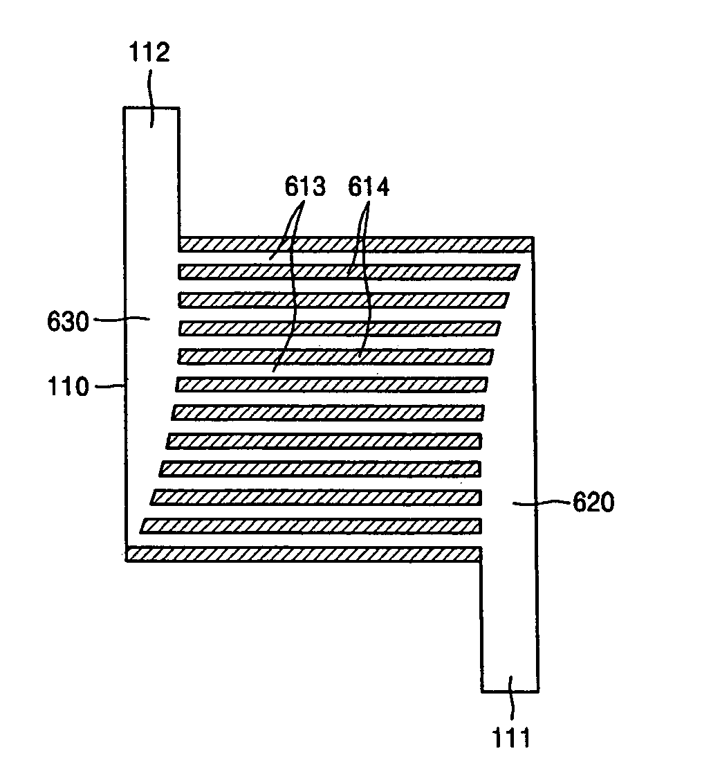
[0032] Referring to FIG. 2, the heat sink apparatus 100 includes a body 110, a plurality of channels 113, an inflow guide unit 120, and an outflow guide unit 130.

[0033] An absorbing fluid enters the body 110 and absorbs heat produced by the electronic device. The body 110 is sealed except for an inlet 111 and an outlet 112 through which the heat absorbing fluid flows.

[0034] The plurality of channels 113 are partitioned at predetermined intervals by a plurality of channel walls 114 inside the body 110 so that the heat absorbing fluid may flow through each of the chan...


PUM


Abstract

A heat sink apparatus is provided for an electronic device. The heat sink apparatus includes a body in which an inlet and an outlet are formed. A heat absorbing fluid flows through a plurality of channels. An inflow guide unit has a cross-section that narrows as it extends away from the inlet to guide substantially the same amount of the heat absorbing fluid into each of the channels. An outflow guide unit formed substantially identically to the inflow guide unit guides the heat absorbing fluid from the channels to the outlet.

Description

CROSS REFERENCE TO RELATED APPLICATION [0001] This application claims the benefit under 35 U.S.C. § 119(a) of Korean Patent Application No. 10-2005-0029954, filed on Apr. 11, 2005 in the Korean Intellectual Property Office, the entire disclosure of which is hereby incorporated by reference. BACKGROUND OF THE INVENTION [0002] 1. Field of the Invention [0003] The present invention relates to a heat sink apparatus for an electronic device. More particularly, the present invention relates to a heat sink apparatus for an electronic device that maintains a uniform flux of a heat absorbing fluid so that the temperature of a surface contacting the electronic device is substantially constant. [0004] 2. Description of the Related Art [0005] Generally, electronic devices of sound devices or amplifiers of communication repeaters or computer electronic devices, such as central processing units (CPUs), graphic cards, power suppliers, and other similar electronic devices, generate heat while opera...

Claims


Application Information

Patent Timeline
Patent Type & Authority Applications(United States)
IPC IPC(8): H05K7/20
CPCH05K7/20254F28F9/0263H05K7/20
Inventor PARK, HEE-SUNGKIM, KWANGKANG, JONG-TAE
Owner SAMSUNG ELECTRONICS CO LTD
Learn More