
Portable motion-activated position reporting device

a technology of motion-activated position and reporting device, which is applied in the direction of navigation instruments, using reradiation, instruments, etc., can solve the problems of prohibitive cost of position reporting device, affecting the accuracy of transcription, and the amount of power consumed by the reporting device, so as to facilitate the movement of the position reporting device, reduce the likelihood of transcription errors, and reduce the amount of time needed

Active Publication Date: 2006-10-05
TRIMBLE NAVIGATION LTD
View PDF9 Cites 63 Cited by
  • Summary
  • Abstract
  • Description
  • Claims
  • Application Information

AI Technical Summary

Benefits of technology

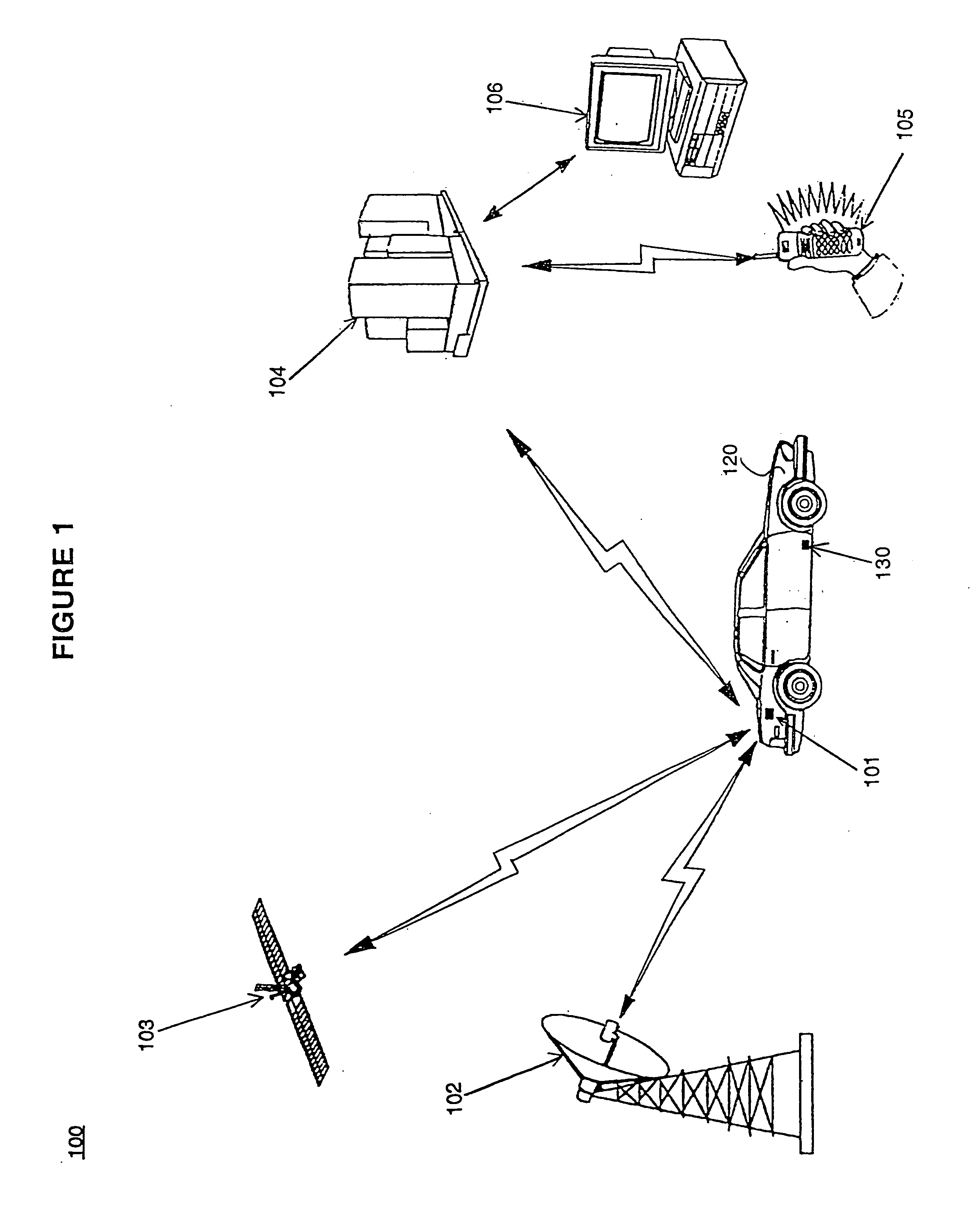
[0009] Accordingly, a need exists for a low-cost portable position reporting device which is small enough to be easily concealed upon an asset which is being tracked. While meeting the above need, it is desirable to provide a position reporting device which requires minimal installation and maintenance on the part of a user and which can be easily moved from one asset to another as needed. Furthermore, a need exists for quickly and accurately identifying which asset is being tracked after the position reporting device has been moved to another asset. While meeting the above needs, a further need exists for a position reporting device with a self contained power source to enable the tracking of assets which can not supply power to the position reporting device. Furthermore, a need exists for a method for reducing the power consumption of the above stated device to extend the usable life of the power source and thus minimize the maintenance needs of the device. Furthermore, a need exists for quickly and accurately identifying which asset is being tracked
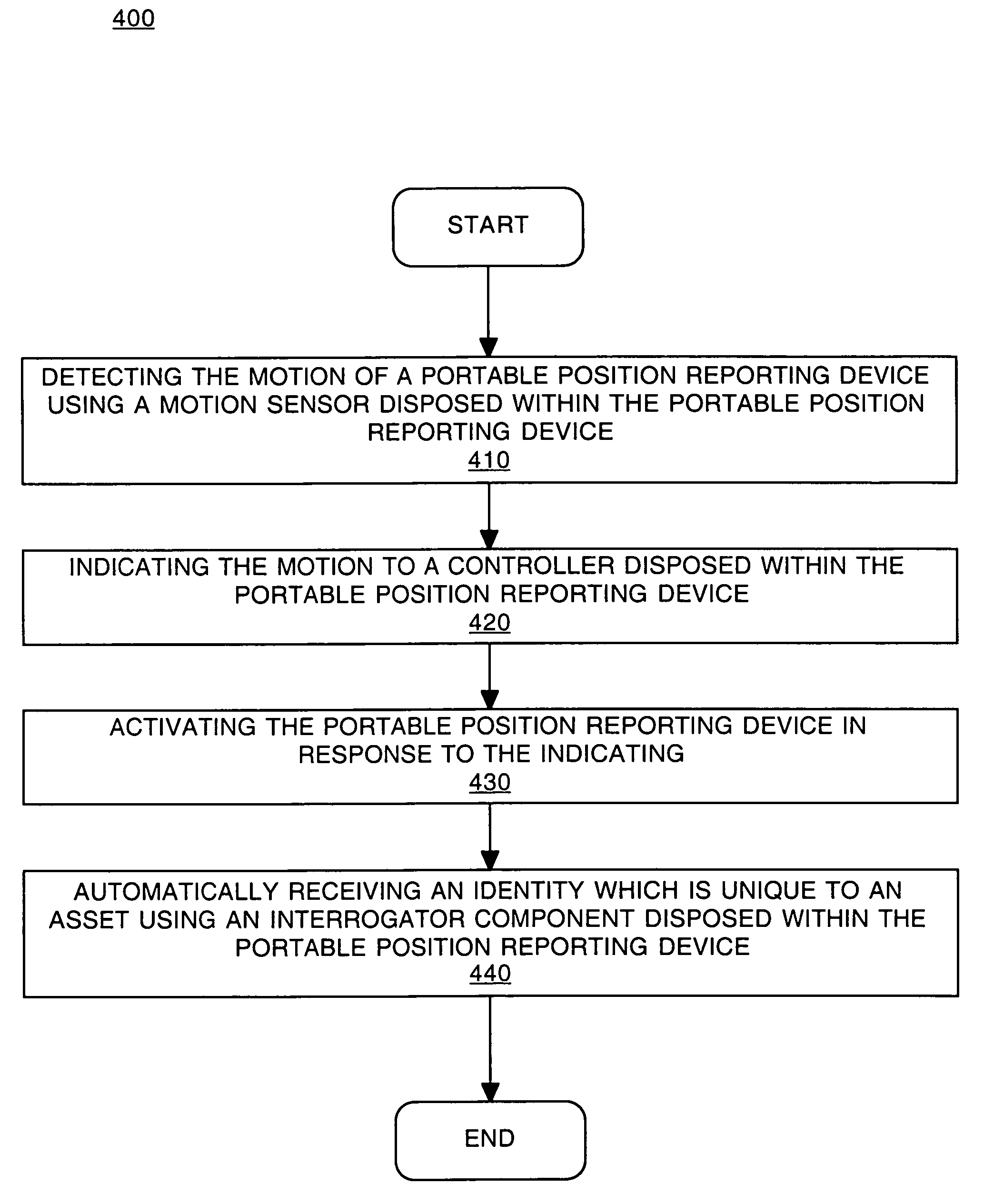
[0012] The position monitoring device uses the interrogator component to wirelessly access the identity of the vehicle when movement of the position monitoring device is detected. As a result, there is no requirement for a human to manually match the identification number of the vehicle with the identification number of the position reporting device. This, facilitates moving the position reporting device from one asset to another by reducing the amount of time needed to identify which asset is being monitored by a particular position reporting device. Additionally, embodiments of the present invention reduce the likelihood of a transcription error when recording the identification numbers of the vehicle and position reporting device and / or matching them in a database.
[0013] Because embodiments of the present invention facilitate moving a position reporting device between a plurality of assets, the cost of operating the position reporting device because a single device can be used to monitor a plurality of assets. Consequently, the need for a dedicated position reporting device for each asset being monitored is reduced.

Problems solved by technology

However, many potential users find the cost of position reporting devices prohibitive compared to the value of the asset being tracked.
Thus, the use of position reporting devices has typically been limited to high value items such as cars or other vehicles.
Another drawback associated with position reporting devices is the amount of power they consume.
While battery powered position reporting devices do exist, the amount of power they consume when turned on necessitates frequent battery changes in order to continue operating.
This makes using position reporting devices inconvenient to some users in that they require an excessive amount of maintenance to continue operating.
Therefore, a dedicated position reporting device for each vehicle is not needed and can be expensive to purchase and maintain.

Method used


Image

  • Portable motion-activated position reporting device
  • Portable motion-activated position reporting device
  • Portable motion-activated position reporting device

Examples


Embodiment Construction

[0019] Reference will now be made in detail to embodiments of the present invention, examples of which are illustrated in the accompanying drawings. While the present invention will be described in conjunction with the following embodiments, it will be understood that they are not intended to limit the present invention to these embodiments alone. On the contrary, the present invention is intended to cover alternatives, modifications, and equivalents which may be included within the spirit and scope of the present invention as defined by the appended claims. Furthermore, in the following detailed description of the present invention, numerous specific details are set forth in order to provide a thorough understanding of the present invention. However, embodiments of the present invention may be practiced without these specific details. In other instances, well-known methods, procedures, components, and circuits have not been described in detail so as not to unnecessarily obscure asp...


PUM


Abstract

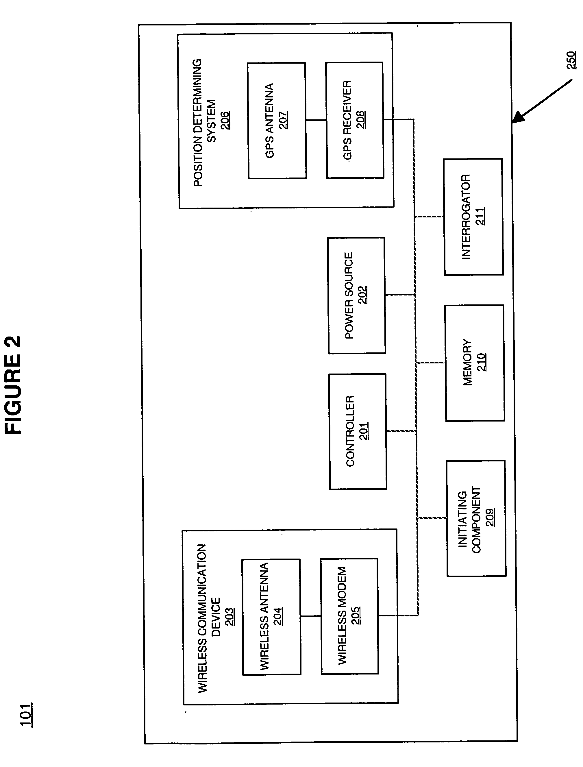
The present invention is a portable motion-activated position reporting device. In one embodiment, a controller is coupled with an interrogator component, a position determining component, a wireless communications component, and an initiating component. In one embodiment, the initiating component detects motion of the position reporting device and generates a signal to the controller indicating the motion. The controller, in response to the signal, activates the interrogator component and the position reporting device.

Description

RELATED APPLICATIONS [0001] The present invention benefits from U.S. Pat. No. 6,801,853 (U.S. patent application Ser. No. 10 / 222,532 filed Aug. 15, 2002) titled “A Portable Motion-Activated Position Reporting Device,” by Dennis Workman, assigned to the assignee of the present invention, and which is hereby incorporated by reference in its entirety herein. [0002] The present invention benefits from U.S. patent application No. TBD filed TBD titled “Geographic Marking Device with RFID Transponder,” by Jeff Hamilton, assigned to the assignee of the present invention, and which is hereby incorporated by reference in its entirety herein.FIELD OF THE INVENTION [0003] Embodiments of the present invention are related to a device for determining and reporting the position of a person or object. BACKGROUND OF THE INVENTION [0004] Position reporting devices are frequently used to locate and report the position of a person or object. A typical position reporting device combines a navigation syst...

Claims


Application Information

Patent Timeline
IPC IPC(8): G01C21/26G01S19/11
CPCG01S5/0027G08G1/205G01S13/758G01S13/756
Inventor WORKMAN, DENNISHAMILTON, JEFFERY ALLEN
Owner TRIMBLE NAVIGATION LTD
Learn More