Control system having virtual power monitor for realizing function to evaluate/analyze stability of control object

a control system and virtual power monitor technology, applied in the field of control systems, can solve the problems of secondary disaster, system is thereafter out of control, and takes a great deal of time and labor to restart the system, so as to ensure the stability of an output, enhance the performance of the user control system, and hold the performance as high

Inactive Publication Date: 2006-10-05
THE RITSUMEIKAN TRUST
View PDF15 Cites 8 Cited by
  • Summary
  • Abstract
  • Description
  • Claims
  • Application Information

AI Technical Summary

Benefits of technology

[0062] As described above, the present invention provides a system construction that can be so constructed as to be completely externally added to an arbitrary existing system and quantitatively evaluates the stability of an output from an arbitrary user's control system on the basis of the monitoring of virtual power by a virtual power monitor and further guarantees the stability of an output from the user's control system. According to the present invention, it is possible to enhance the performance of the user control system as much as possible or to hold its performance as high as possible within a range in which stability can be held.
[0063] The conceptual diagram of the above-described virtual power monitor system of the present invention is shown in FIG. 8. The whole

Problems solved by technology

Moreover, there is also a possibility that once a limiter is activated in a system, the system is thereafter out of control and causes a secondary disaster.
Even if the system does not come to cause a disaster, in many cases, it takes a great deal of time and labor to restart the system.
Further, the energy balance monitor of the non-patent document 2 secures the passivity of a transmission line between a master and a slave and the passivity observer/passivity controller of the non-patent document 3 secures the passivity of virtual space of a haptic system, respectively, but they do not guarantee the stability of a control

Method used


Image

  • Control system having virtual power monitor for realizing function to evaluate/analyze stability of control object
  • Control system having virtual power monitor for realizing function to evaluate/analyze stability of control object
  • Control system having virtual power monitor for realizing function to evaluate/analyze stability of control object

Examples


first embodiment

1. FIRST EMBODIMENT

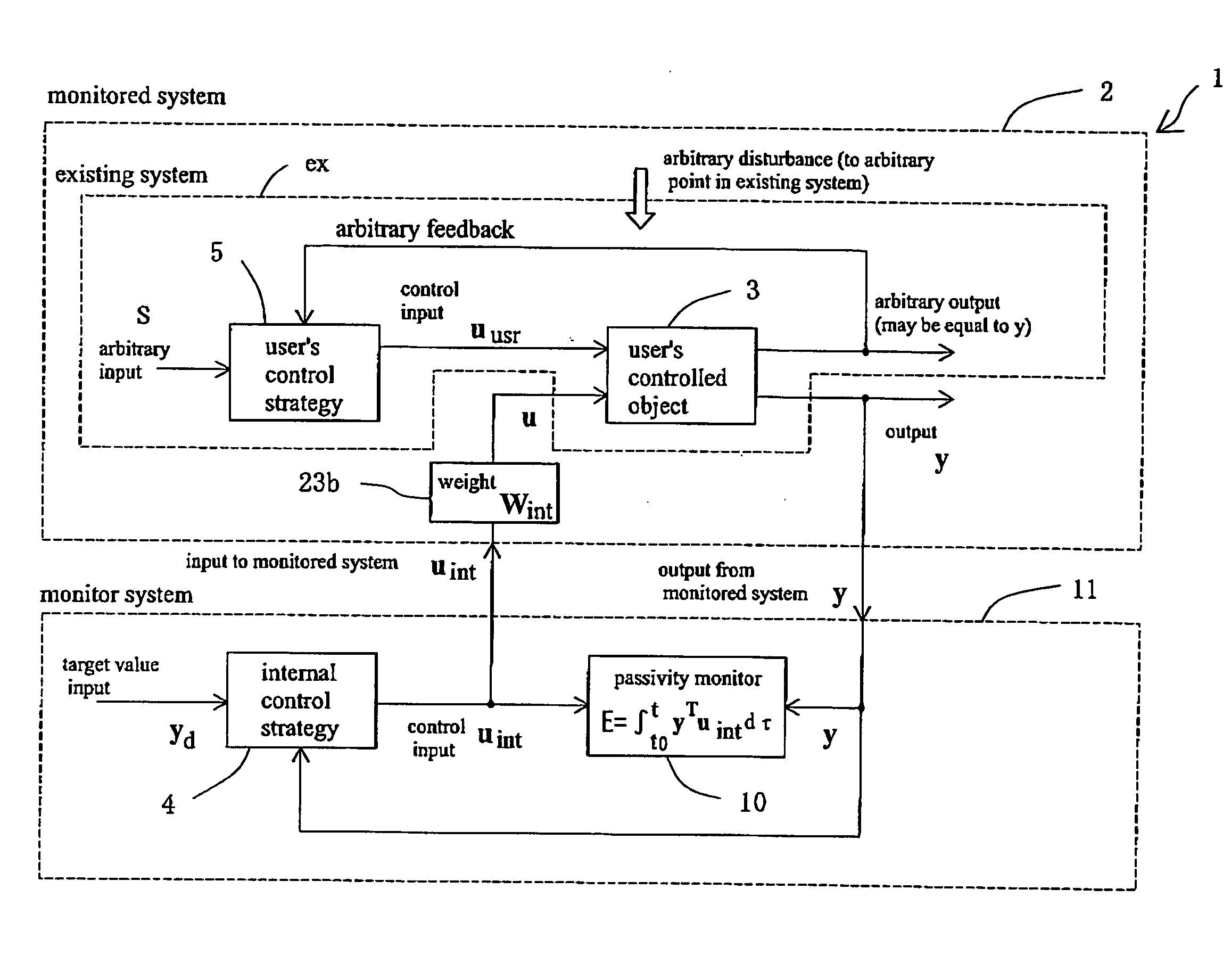
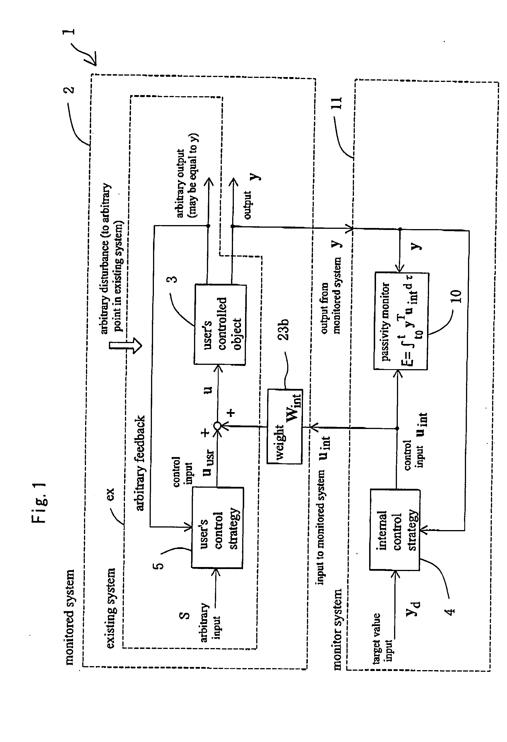
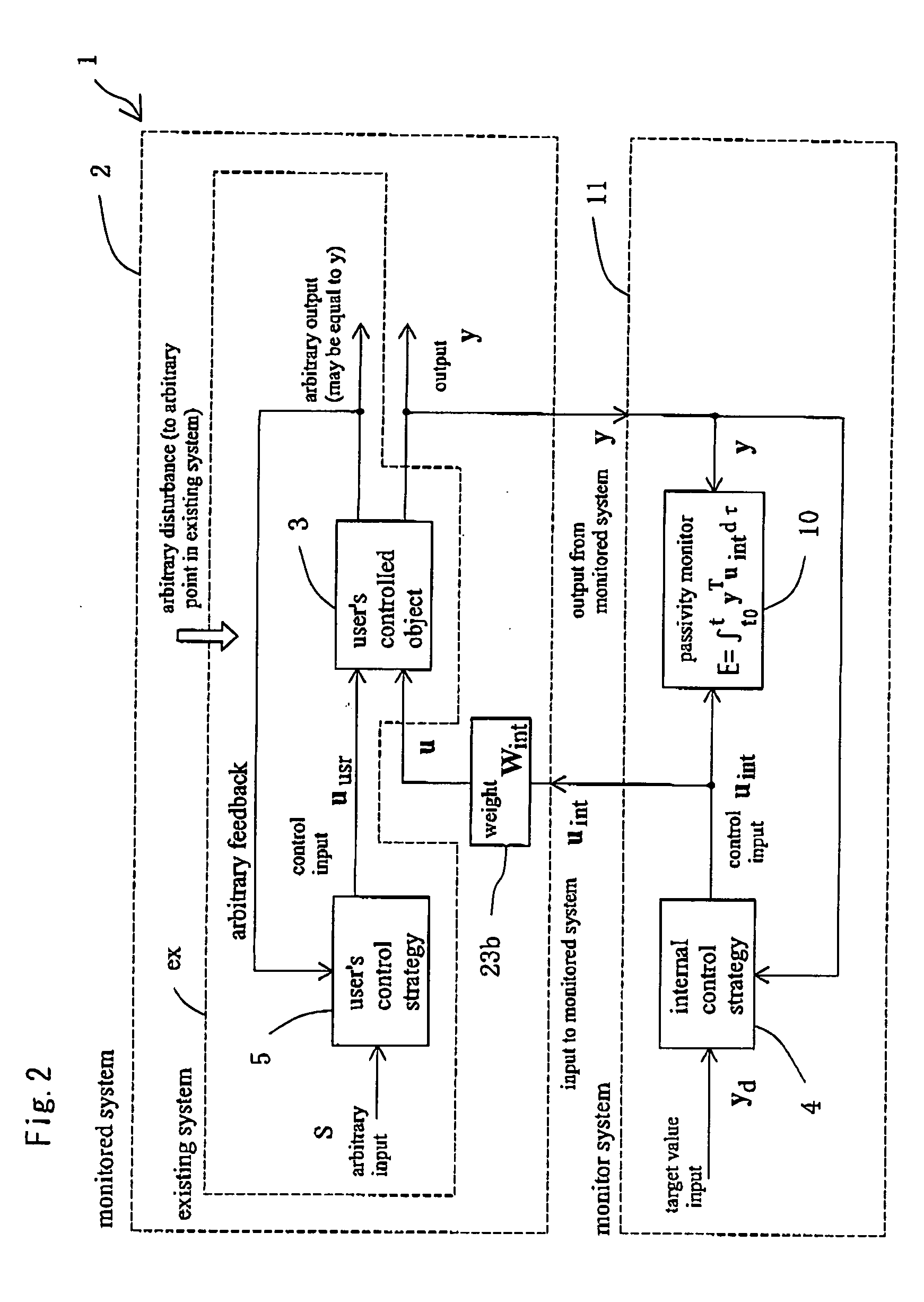
[0085] Hereafter, one embodiment and its operation of the present invention in a robot control system, which is a typical example of the object to which the present invention is applied, will be described on the basis of FIG. 1 to FIG. 7. A control system 1 in accordance with the present invention is characterized mainly in that a passivity monitor and a software limiter are added to an existing system ex. First, 1) the reason why the stability of a control system can be quantitatively evaluated by a passivity monitor will be described, and then 2) the reason why the stability of an output of a monitored system can be guaranteed by a software limiter will be described.

[0086] Here, FIG. 1 to FIG. 5 show individual configurations of a passivity monitor 10 and software limiters (21a, 21b to 24a, 24b). Moreover, the respective constituent elements shown in FIG. 6 and FIG. 7 construct the control system 1 of the present invention in combination. FIG. 1 shows a control...

second embodiment

2. SECOND EMBODIMENT

[0109] Next, a virtual power limiter system that is newly defined by generalizing a system including the above-described passivity monitor and software limiters and guarantees the stability of a control system will be described.

[0110] First, a virtual power monitor (corresponding to the passivity monitor 10 of the first embodiment), which is one constituent element of the virtual power limiter system of the present invention, will be described.

[0111] In FIG. 8 is shown a user's control system 2′ having a virtual power monitor 110 added thereto. Assume that a control input from a conservative control strategy 104, which is designed separately from the user's control strategy 5, is ucsv (t). The control input ucsv from the conservative control strategy 104 does not need to be necessarily inputted in reality to the user's controlled object 3 but is virtually connected to the user's controlled object 3.

[0112] Here, the quantity of monitoring by the virtual power m...

embodiment 1

[Various User's Control Systems to Which the Virtual Power Limiter System is Applied]

[0139] Hereafter, one embodiment of the present invention will be described with reference to the accompanying drawings.

[0140] Here, in the descriptions of the respective following examples, the same parts as in FIG. 1 to FIG. 10 are denoted by the same reference symbols and the like.


PUM


Abstract

A system configuration can evaluate the stability of an output from a user's control system including all effects of unknown dynamic characteristics and disturbances and can guarantee the stability of the output from the user's control system irrespective of the unknown dynamic characteristics and the disturbances. The control system is provided with a virtual power monitor and is thereby provided with a function of evaluation and analyzing the stability of an object to be controlled, and is such that in a user's control system the user's controlled object is controlled by the user's control strategy. Included is a conservative control strategy which receives a feedback signal from the user's controlled object and can input a control input to the user's controlled object; and a virtual power monitor which monitors power virtually transmitted from the conservative control strategy to the user's controlled object, and can evaluate the stability of an output from the user's control system.

Description

TECHNICAL FIELD [0001] The present invention relates to a common control system in a mechanical field, an electric and electronic field, a chemical field or the like. The present invention can be applied to a wide variety of control systems of, for example, robots, machine tools, automobiles, electric and electronic circuits, chemical plants and the like. BACKGROUND ART (Non-Patent Document 1][0002]“Control Theory of Non-linear Mechanical Systems—A Passivity-based and Circuit-theoretic Approach”, by S. Arimoto, Oxford Science Publication, 1996. (Non-Patent Document 2][0003]“Bilateral Control with Energy Balance Monitoring Under Time-Varying communication Delay”, by Y. Yokokohji, T. Imaida, and T. Yoshikawa, Proceedings of the 2000 IEEE International Conference on Robotics and Automation, page 2684-2689, 2000. [Non-Patent Document 3][0004]“Control of a Flexible Manipulator with Noncollocated Feedback: Time Domain Passivity Approach”, by J. H. Ryu, D. S. Kwon, and B. Hannaford, Con...

Claims


Application Information

Patent Timeline
IPC IPC(8): G05B11/01G05B13/02G05B5/01
CPCG05B5/01
Inventor KANAOKA, KATSUYAYOSHIKAWA, TSUNEO
Owner THE RITSUMEIKAN TRUST
Why Eureka
Try Eureka