
Exposure system and exposure method

a technology of exposure system and exposure method, which is applied in the field of exposure system ad method, can solve the problems of increasing the size of the chamber, the inability to perform the exposure operation and the alignment measurement apparatus simultaneously, and the inability to achieve the effect of adjusting the position of the stage arrangemen

Inactive Publication Date: 2006-10-05
CANON KK
View PDF10 Cites 7 Cited by
  • Summary
  • Abstract
  • Description
  • Claims
  • Application Information

AI Technical Summary

Benefits of technology

[0020] According to the preferred embodiment of the present invention, the calculating step can corrects the position of the region, obtained based on the first measurement, based on the first measurement and the second measurement.

Problems solved by technology

When the exposure apparatus is configured to comprise a single substrate stage, it cannot perform the exposure operation and alignment measurement apparatus simultaneously.
When the exposure apparatus comprises two stages, it can perform the exposure operation and alignment measurement operation simultaneously, but the size of its stage arrangement becomes inevitably large.
An increase in chamber size leads to a bulky vacuum device or purge device which maintains the inner space of the chamber at a predetermined vacuum degree or atmosphere.
In addition, an increase in chamber size increases the time required to change the inner space of the chamber from the atmospheric environment to a predetermined reduced-pressure environment or atmosphere when the exposure apparatus is started.
If the substrate size changes, a value obtained by alignment measurement in the atmosphere may include an error in the exposure chamber.

Method used


Image

  • Exposure system and exposure method
  • Exposure system and exposure method
  • Exposure system and exposure method

Examples


Embodiment Construction

[0028] The preferred embodiment of the present invention will be described with reference to the accompanying drawings.

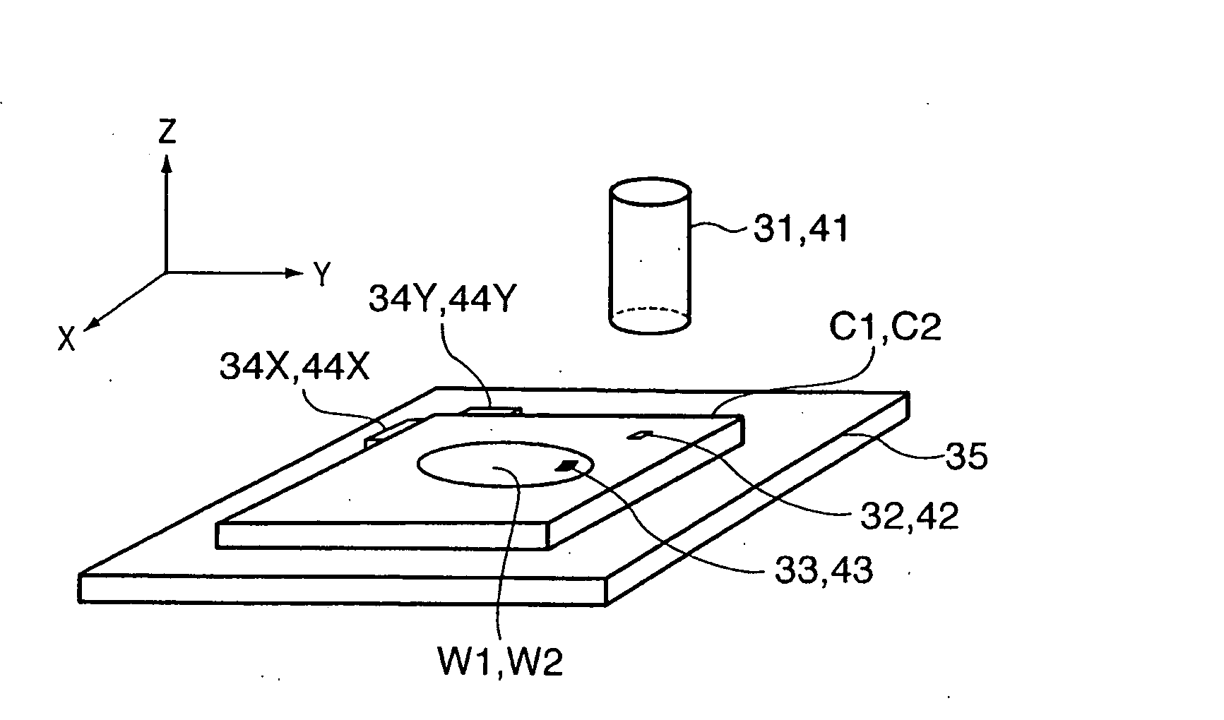
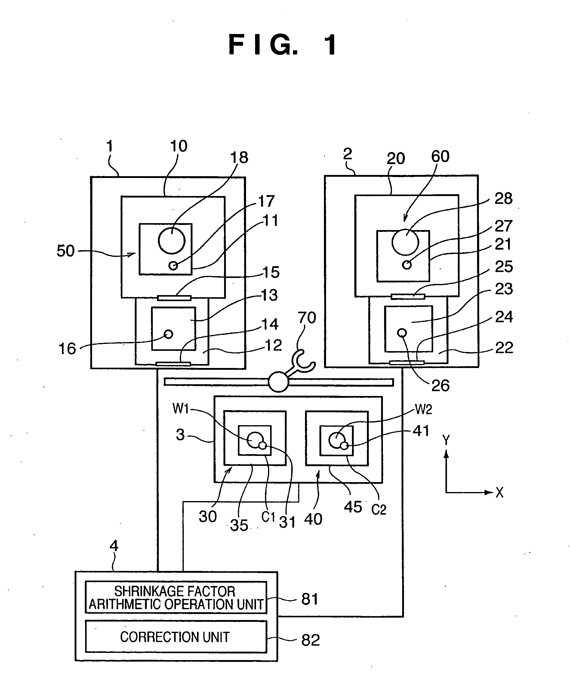
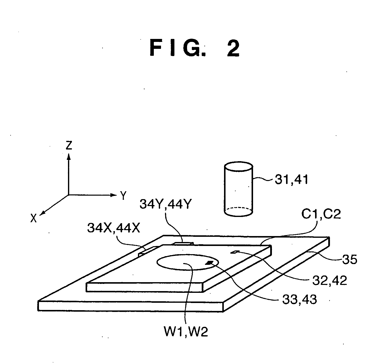
[0029]FIG. 1 is a view showing the schematic arrangement of an exposure system according to a preferred embodiment of the present invention. The exposure system according to the preferred embodiment of the present invention includes at least one exposure apparatus, preferably, a plurality of exposure apparatuses 1 and 2, an alignment measurement device 3, and a controller 4.

[0030] The exposure apparatus 1 forms a latent image pattern by photosensitizing a photosensitive agent applied to a substrate (e.g., a wafer or glass plate) with an exposure beam, and can be configured as, e.g., an electron beam exposure apparatus. An exposure unit 50 as the main body portion of the exposure apparatus 1 can be configured to include a substrate stage 11 which drives the substrate, a projection system 18 which projects the exposure beam such as an electron beam onto the substrat...


PUM


Abstract

An exposure system for exposing a substrate to radiation is disclosed. The system comprises an exposure unit configured to expose the substrate to radiation, an exposure chamber configured to accommodate the exposure unit, an alignment measurement unit arranged outside the exposure chamber and configured to measure a position of an alignment mark on the substrate, and a load-lock chamber arranged between the exposure chamber and the alignment measurement unit.

Description

FIELD OF THE INVENTION [0001] The present invention relates to an exposure system ad method such as, for example, an exposure system and method for exposing a substrate coated with a photosensitive material to radiation such as charged particles, an F2 laser light, or EUV (extreme ultraviolet) light. BACKGROUND OF THE INVENTION [0002] An exposure apparatus used to manufacture a device such as a semiconductor device comprises an exposure unit, alignment measurement unit, substrate stage, and the like. The exposure unit includes an exposure light source, illumination system and projection optical system. An exposure beam containing pattern information is generated by an exposure light from the light source illuminating an original plate having a pattern. The projection system projects the exposure beam containing the pattern information of the original plate onto a substrate. The alignment measurement unit measures the position of an alignment mark formed on the substrate before expos...

Claims


Application Information

Patent Timeline
IPC IPC(8): G03B27/52G03B27/42
CPCG03F7/70808G03F9/7096G03F9/7046
Inventor YAMAGUCHI, KINYATAKAMURA, YUICHI
Owner CANON KK
Learn More