
Spare brake beam having replaceable brake heads

a technology of brake head and spare beam, which is applied in the direction of railway braking system, railway components, transportation and packaging, etc., can solve the problems of difficult to just decouple the damaged brake head, high cost and time consumption, and difficulty in dismantling the brake head, so as to avoid the dismantling, quickly and easily install, and quickly and easily replace the

Active Publication Date: 2006-10-05
STUCKI DE MEXICO S DE R L DE C V
View PDF9 Cites 17 Cited by
  • Summary
  • Abstract
  • Description
  • Claims
  • Application Information

AI Technical Summary

Benefits of technology

[0026] It is therefore a main object of the present invention to provide a brake beam including means for avoiding the dismantling of the same which can be quickly and easily installed in the boogie of a train car, and whose brake head can be quickly and easily replaced in a train car without the necessity of replacing the whole brake beam and consequently without cutting the car from the train nor dismantling the car nor the truck.
[0027] It is another main object of the present invention to provide a brake beam which can be installed without dismantling the car and therefore the operation can be carried out without cutting the car from the train thus saving money on labor and materials, and whose brake head which can be replaced in matter of minutes, saving time on all type of freight cars using a standard type brake beam, being particularly beneficial on intermodal or premium service trains and avoiding penalties and costs related with previous brake beams.
[0028] It is still a main object of the present invention to provide a brake beam thanks to which, it is possible, when installed in the car, to replace the brake head which is found at a damaged condemnable condition under a car in service, by a simple torch cut off process of the pin holding the damaged brake head of the beam under the car, pulling then the damaged component from the car bottom, which activity is simple and familiar to must skilled in the car repair art, and be then able to install the spare brake head of the present invention, as an spare brake beam, right there and then, without the dismantling of the train, car nor truck, with simple common tools and skills.
[0029] It is still another main object of the present invention to provide a brake beam thanks to which there are avoided the accidents and personal injuries to the maintenance staff related to car dismantling operations.
[0030] It is an additional object of the present invention to provide a brake beam having a replaceable brake head in which thanks to the DTI included in each brake head coupling section, when it is necessary to replace the brake head, the bolt that joins the brake head to the brake beam can be adjusted at the correct tension without the need of checking it with a feeler gauge or to loosing and tightening the bolt repeatedly until the correct tension is achieved.

Problems solved by technology

The above referred operation is a main cause for car repair personnel injuries, it's very complex, it's costly and time consuming since it may take from 3 to 7 days to replace a brake beam.
And worst, the owner of the car and the transport company, looses money for each minute the car is inactive, besides angry customers since usually the car that is cut from the train is completely loaded, facing penalties or damaged perishable goods.
When it is necessary to replace a brake head welded to the brake beam, normally the whole brake beam is replaced since it is extremely difficult to detach a welded brake head from the brake beam.
For brake beams having brake heads linked by bolts, when it is necessary to replace a brake head due to a worn out condition, it is very difficult to just decouple the damaged brake head since the bolts are usually not designed to be retired from the brake beam.

Method used


Image

  • Spare brake beam having replaceable brake heads
  • Spare brake beam having replaceable brake heads
  • Spare brake beam having replaceable brake heads

Examples


Embodiment Construction

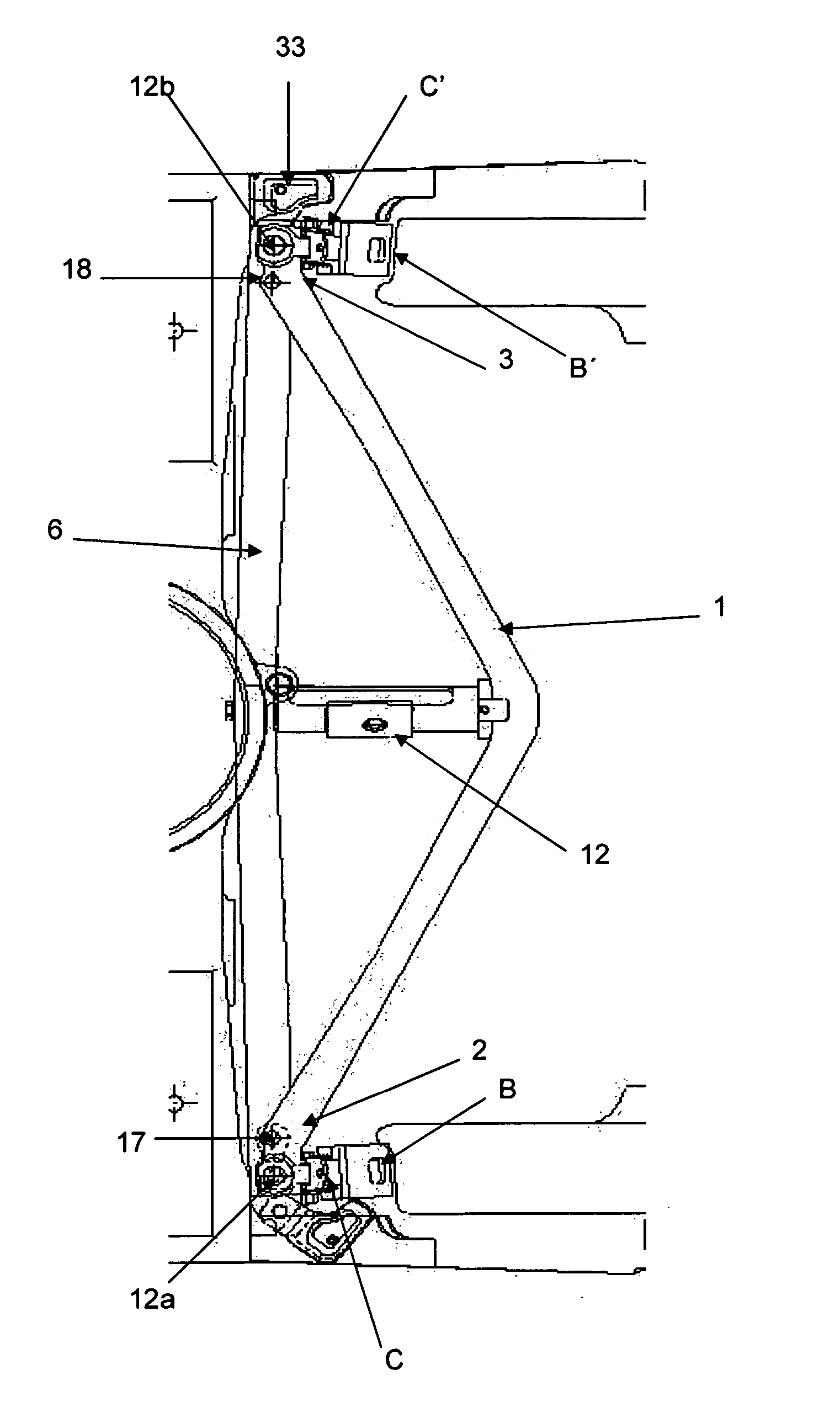
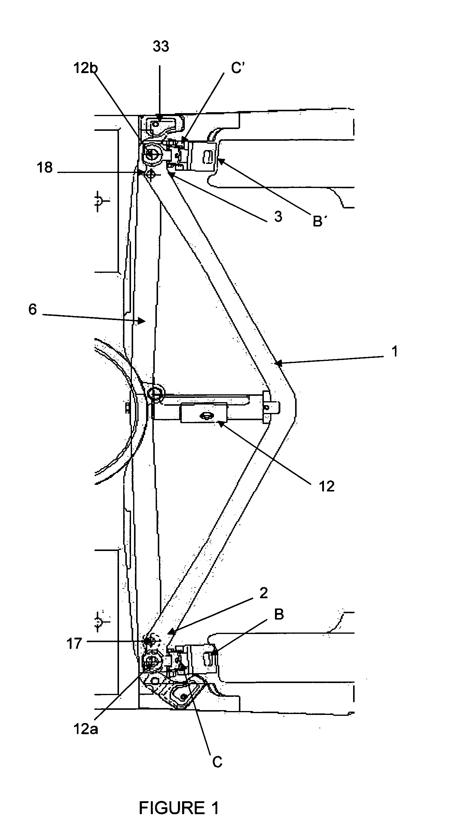
[0040] The brake beam of the present invention will now be described making reference to a common brake beam, in accordance with its most general embodiment thereof illustrated in the accompanying drawings wherein the same signs and numbers, refer to the same parts of the shown figures, comprising:

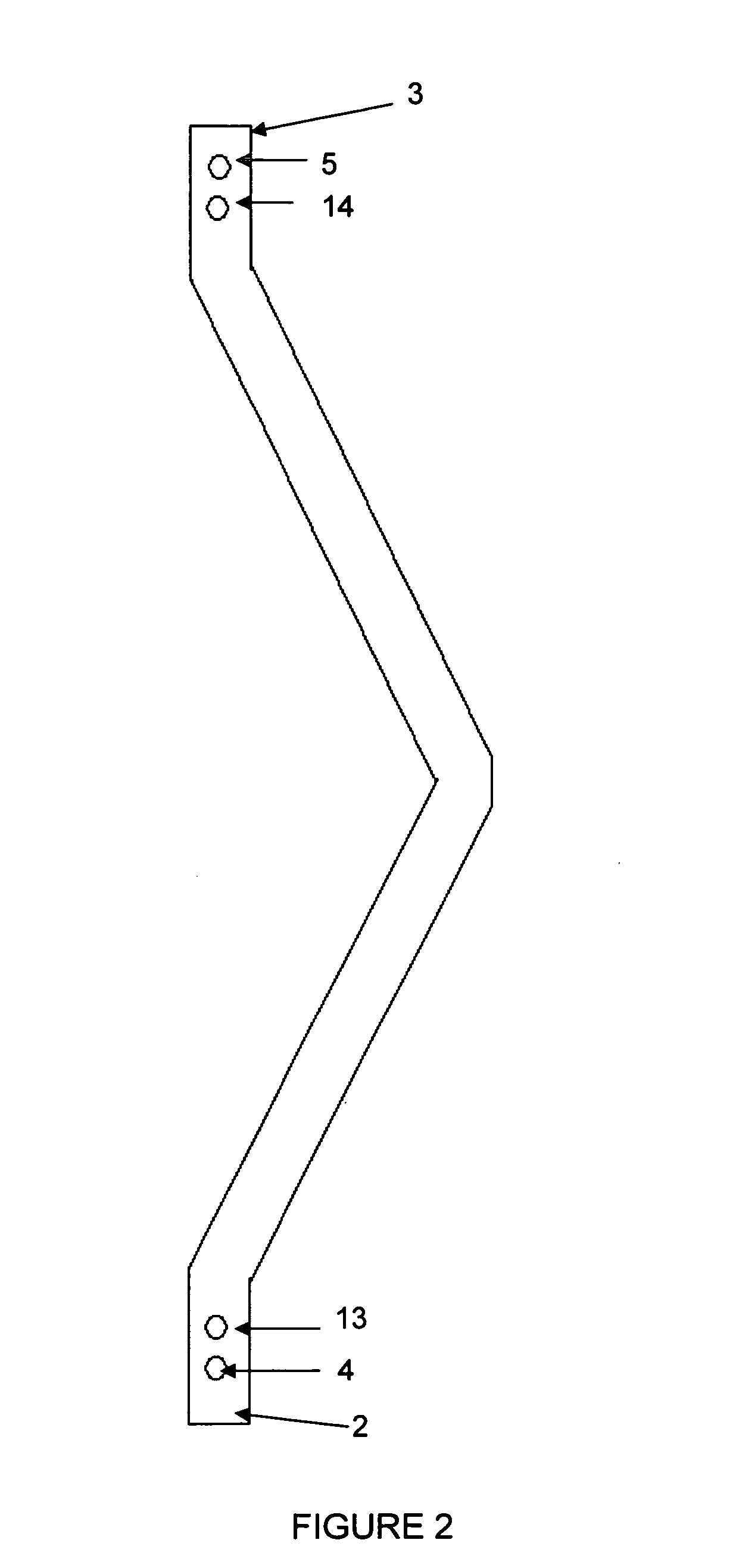
[0041] a “V” shaped tension member 1 having a first end 2 and a second end 3, said “V” shaped tension member 1 having a channel shaped cross section (not shown) including a lower wall and two upwardly projecting side walls, each depending from an edge of the lower wall, and including a first 4 and a second pair 5 of opposite holes each hole located in opposite side walls opposite to each other and each pair located near the ends 4, 5 of the tension member 1;

[0042] a compression member 6, having a first end 7 and a second end 8 coinciding with the first 2 and second end 3 of the tension member 1, a channel shaped cross section (not shown) including an upper wall and two depending side wal...


PUM


Abstract

A brake beam including means for allowing the brake head to be replaced without effort and to include replaceable brake heads.

Description

BACKGROUND OF THE INVENTION [0001] A. Field of the Invention [0002] The present invention is related to brake beams for railway cars, and more particularly to a brake beam which allows a quick installation thereof and a quick replacement of its brake head if required. [0003] B. Description of the Related Art [0004] There are well known brake heads assemblies for railway cars by which a brake shoe is pressed against a wheel in order to decrease or stop the rotational speed of the wheel and railway car. [0005] Generally, the brake head assembly is held by a structure called “brake beam” mounted transversely in the bogie of a railway car and is linked to a lever, which applies a force in order to press the brake shoe against a wheel. [0006] The brake beam generally comprises, a generally “V” shaped tension member a compression member having its ends coupled to the ends of the tension member, a brake head subassembly linked to the each end of the compression member, two end extensions e...

Claims


Application Information

Patent Timeline
Patent Type & Authority Applications(United States)
IPC IPC(8): B61H13/36
CPCB61H13/36
Inventor DE LA FUENTE-FARIAS, JORGE
Owner STUCKI DE MEXICO S DE R L DE C V
Learn More