
Devices and systems for remote and automated monitoring and control of water removal, mold remediation, and similar work

a technology of remote and automated monitoring and control, applied in the direction of instruments, nuclear elements, digital computer details, etc., can solve the problems of many buildings, severe burden on owners, occupants, and serious damage caused

Inactive Publication Date: 2006-09-28
ARMSTRONG JAY T
View PDF11 Cites 40 Cited by
  • Summary
  • Abstract
  • Description
  • Claims
  • Application Information

AI Technical Summary

Benefits of technology

[0018] Electronic devices and methods are disclosed that will enable remote and / or automated monitoring of temperature and humidity inside a building during a water remediation operation, such as after a flood, burst pipe, or discovery of a large mold colony. The electronic devices comprise a set of sensor / processor devices that can be placed in a room or building that is being dried out and remediated, and that can measure temperature and humidity inside the room or building. These devices will also comprise, or be coupled to, a communication device that will allow a technician to obtain recently gathered data via suitable remote means (such as by telephone or internet contact, via a radiofrequency transmission, etc.), without having to travel to the site. A processor at a remediation site can gather data from a plurality of sensors that are positioned in different locations around a room or building, if desired, and a coordinating data collection and processing system (which can be carried around on a laptop computer, if desired) can gather data that is being gathered at any number of job sites, and can organize and distinguish the different data sets from each site.

Problems solved by technology

In America and elsewhere, serious damage is caused each year to many buildings, and severe burdens are placed on the owners, occupants, and users of those buildings, by problems relating to water.
Any of these types of events or conditions can lead to structural damage to wood, dry wall, or other materials, the growth of noxious colonies of mold of other microbes, the formation of foul odors, etc., and those problems in turn can trigger asthma attacks, respiratory problems, and other health problems.
This approach to monitoring the atmospheric conditions in a room or building during water remediation is labor-intensive, and is relatively time-consuming, expensive, distracting, and burdensome.
In addition, it becomes even more troublesome if a job site is a long distance away from a contractor's office (which happens fairly often, especially in rural areas).
Since most workers who do that type of work are not especially fond of handling and filling out that kind of paperwork, the data are not always reliably gathered and recorded, and the data also can be (i) limited by the capabilities and memory capacity of the portable sensor, and / or (ii) rendered erroneous and misleading, if a portable electronic device is handled roughly, or if it gradually drifts out of calibration.
However, except for basic repairs (such as checking to make sure any power cords are fully plugged in, any circuit breakers have not been tripped, etc.), such workers usually are not trained, qualified, or equipped to repair that type of electrical equipment if it malfunctions.
In addition, problems such as tripping of a circuit breaker (thereby shutting down power equipment that is crucial to the remediation) often do not occur while a worker is present, and it should be noted that such occurrences are fairly common, if a flood or burst pipe allowed water to permeate into sockets, switches, junction boxes, or other wiring or appliances.
Those types of shutdowns, if not detected quickly, can lead to extended periods of lost and wasted time, which will slow down a remediation, and which can create serious problems and disputes between homeowners, contractors, and insurance companies.

Method used


Image

  • Devices and systems for remote and automated monitoring and control of water removal, mold remediation, and similar work
  • Devices and systems for remote and automated monitoring and control of water removal, mold remediation, and similar work
  • Devices and systems for remote and automated monitoring and control of water removal, mold remediation, and similar work

Examples


Embodiment Construction

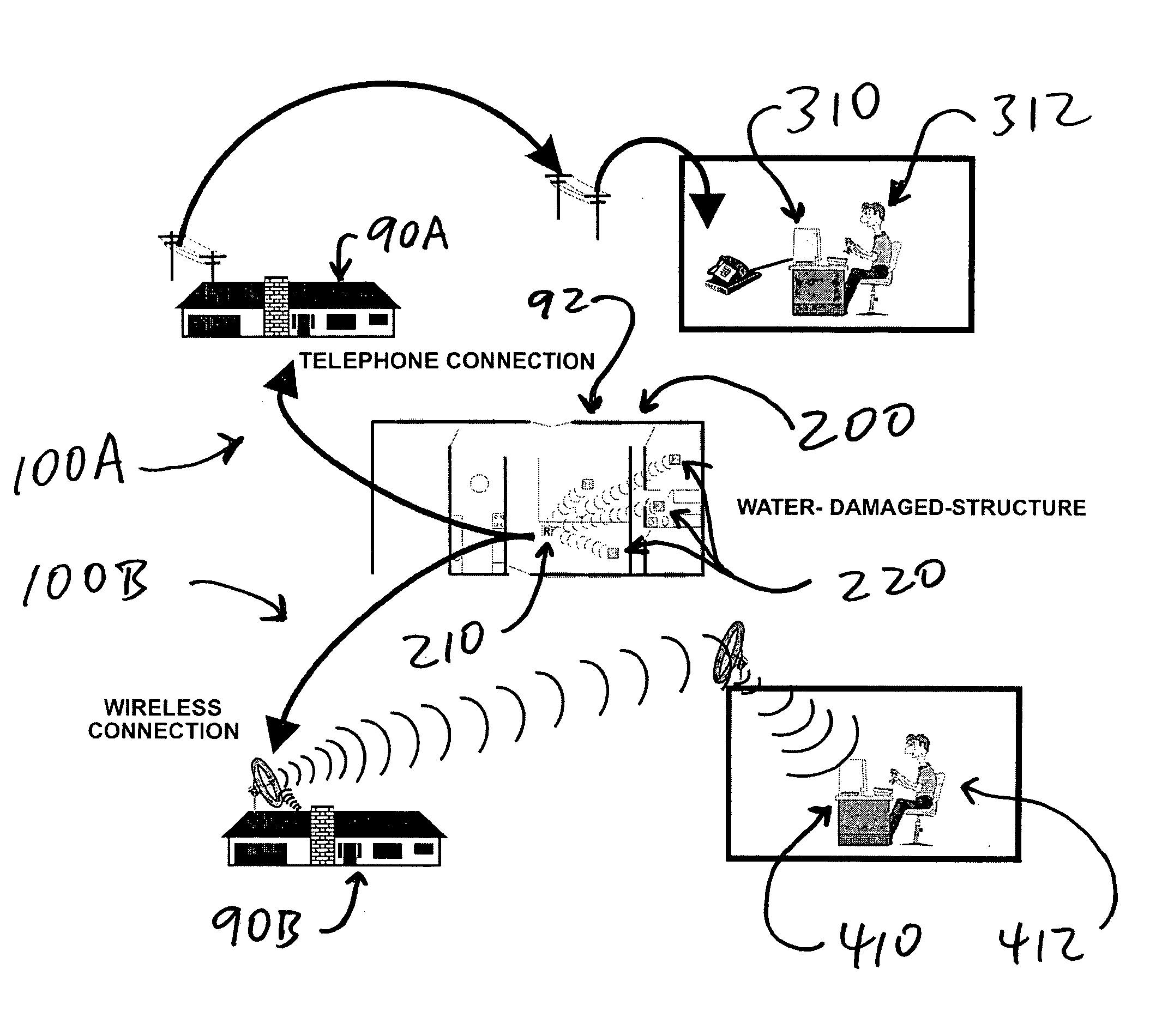
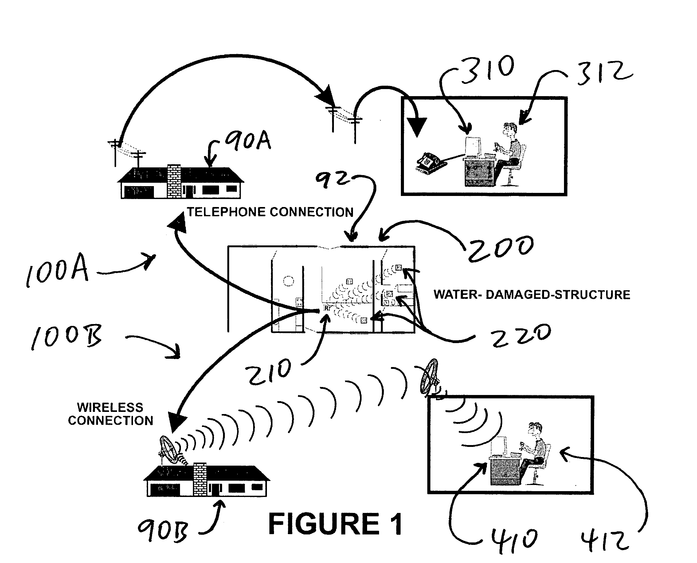
[0024] As briefly summarized above, electronic devices and systems are disclosed that will enable automated and / or remote measuring and monitoring of air temperature and humidity levels in a water-damaged building. A simplified schematic of such a system, represented by callout numbers 100A (for a hard-wired system that uses telephone lines) or 100B (for a wireless system that uses cell-phone or other radiofrequency transmission), is provided in FIG. 1.

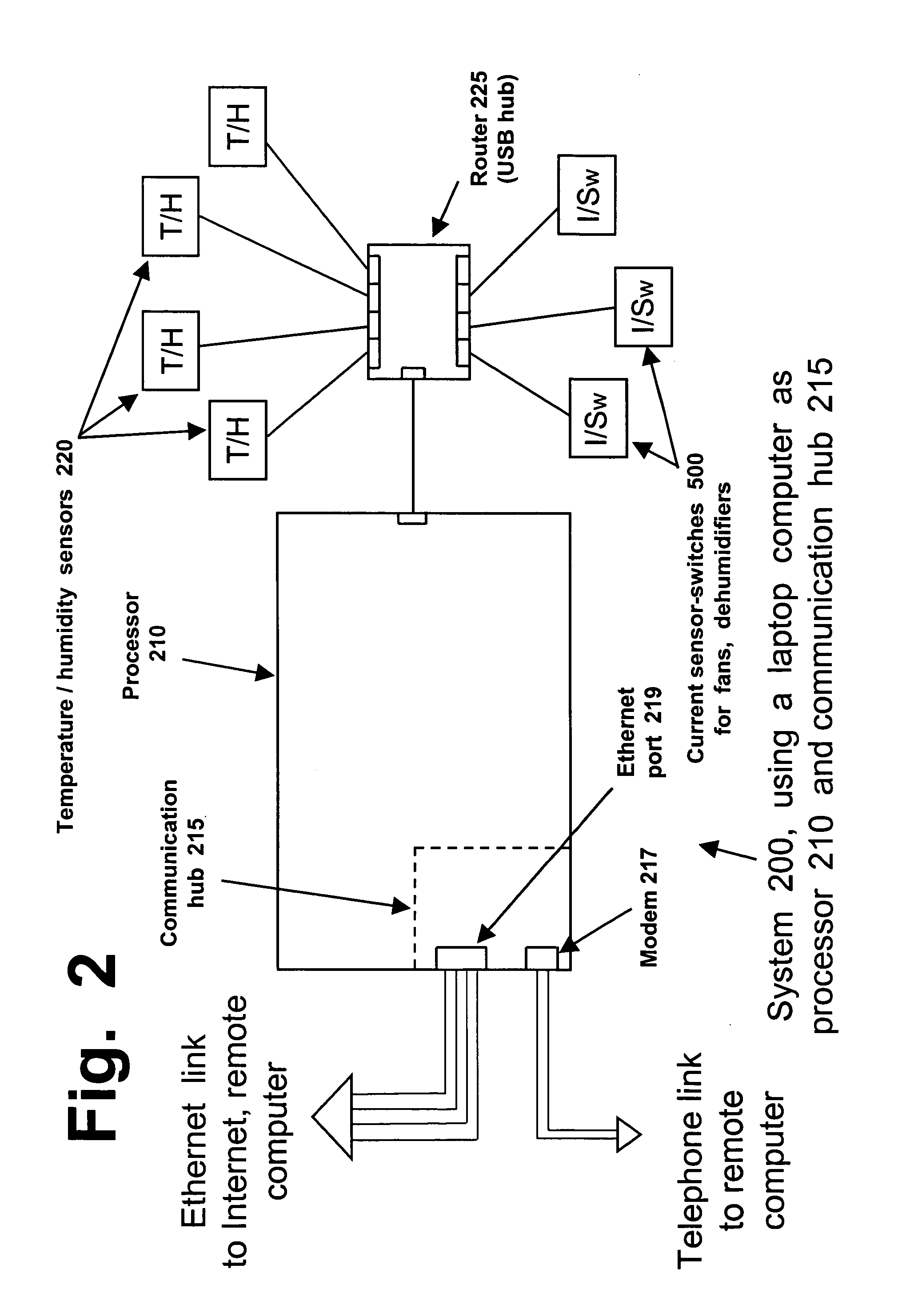
[0025]FIG. 1 depicts a home 90 that has been damaged by a flood, burst pipe, a major mold infection, or other water intrusion or damage. Callout number 90A represents home 90 in which a hard-wired telephone connection is being used, while callout number 90B represents home 90 where a wireless system is being used. Floorplan 92 represents a basement or ground floor having several different rooms that require remediation. Sensor and transmitter system 200, shown in more detail in FIG. 2, has been installed at the job site. The system 2...


PUM


Abstract

Electronic devices, systems, and methods are disclosed for remote and / or automated monitoring of temperature, humidity, or other factors in a building during a remediation project, such as after a flood or mold infestation. These devices comprise sensors devices that can be distributed around a room or building, for transmitting data to a processor such as a laptop computer. Using telephone, cell phone, or internet connections, the processor can transmit compiled data to a website or remote computer, for analysis and use by a project supervisor. Sensor-switch devices also are disclosed for turning fans, dehumidifiers, or other equipment on or off. Using a telephone, cell phone, or internet connnection, a project supervisor at any location can download information, obtain current status information, and turn equipment on or off as needed.

Description

FIELD OF THE INVENTION [0001] This invention is in the field of electronic monitoring devices, and involves devices that can assist in cleanup and remediation of a building that has been damaged by a flood, mold infestation, or similar problem involving excessive water or moisture. BACKGROUND OF THE INVENTION [0002] In America and elsewhere, serious damage is caused each year to many buildings, and severe burdens are placed on the owners, occupants, and users of those buildings, by problems relating to water. The types of problems that can lead to water damage include but are not limited to flooding, bursting of water pipes due to freezing, corrosion, or other problems, water seepage into buildings (and especially basements) after rains, water condensation on cold pipes or other surfaces, punctures in dryer vents or other types of ducting, etc. Any of these types of events or conditions can lead to structural damage to wood, dry wall, or other materials, the growth of noxious coloni...

Claims


Application Information

Patent Timeline
Patent Type & Authority Applications(United States)
IPC IPC(8): G06F15/00
CPCF24F2011/0068F24F2011/0091G05D22/02G08B21/20F24F11/56F24F11/52E04B1/7007
Inventor ARMSTRONG, JAY T.
Owner ARMSTRONG JAY T
Learn More