
Lap counter system for multiple runners

a technology for a runner and a lap counter, which is applied in the field of multiple runner lap counter systems, can solve the problems of significant time investment disadvantage, significant limitations of both technology categories and respective devices, and high cost of commercially available gps devices

Inactive Publication Date: 2006-09-28
TRAKSTARR FITNESS SYST
View PDF15 Cites 43 Cited by
  • Summary
  • Abstract
  • Description
  • Claims
  • Application Information

AI Technical Summary

Benefits of technology

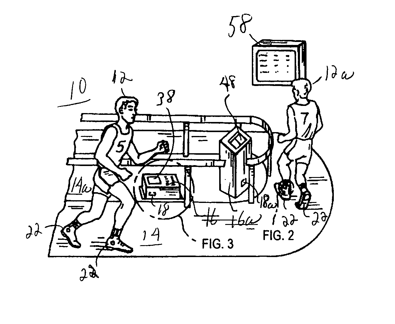
[0013] In accordance with the present invention, the foregoing objects are met by providing a lap counter system for counting and timing a runner's laps around a track in which the runner affixes either a passive or active transponder tag, respectively, to the person or the clothing worn by the person and in which the runner passes by an antenna generally incorporated into a receiver located adjacent the track to pick up the signal emitted from the tag during each lap around the track. Each tag is encoded with unique information related to a particular individual runner and this tag serves as a transponder with the runner's information concerning the counting and timing of the laps associated with each exercise workout session so that this lap information can be logged into a storage device in the system associated with each runner assigned tag. This logging function permits each runner's data for one or more exercise workout sessions to be stored for later comparison between various workout sessions to see the advancement in physical training for each runner. A signal from the runner's tag is generally picked up by an antenna of a predetermined configuration or array generally incorporated into a receiver located closely adjacent the running track.

Problems solved by technology

There are significant problems and limitations with both technology categories and the respective devices used therein.
First, each device shares the disadvantage of a significant investment of time to learn the operation and of money by the runner to purchase a component of these systems.
Next, commercially available GPS devices are quite expensive and generally take the shape of a wristwatch or a band attached around an arm of the runner.
GPS devices although accurate in calculation of speed and location are somewhat delicate instruments that require significant time to calibrate before they can provide reliable data to the runner.
Such devices are limited to only outdoors track where there are no overhead obstructions to impede the reception of satellite signals that often require at least three satellite captures of the signal for a proper triangulation of the runner on the ground.
On the other hand, the modern inertia detection devices are essentially more elaborate electronic versions of the classic pedometer with all of the normal problems encounter by the electronic GPS devices and yet having additional unique problems for the runner that makes inertia devices unfriendly to the end user.
If the runner changes stride during the workout, which is often the case because the runner either speeds up or slows down, there is little chance that the inertia device no matter how expensive the electronics can properly compensate for this change in the runner's stride.
Therefore, the runner ends up with essentially erroneous data displayed and later logged out to a PC for printing the exercise workout session results.
And then there are even more expensive type of runner systems used in Marathon running, cycling and other similar type athletic events marketed by ChampionChip World of the Netherlands.
Since this type of system utilizes expensive components to energize and capture a signal from a chip on board the runner that has a coil which must be energized by a magnetic field at the finish line, a powerful magnetic field must be created and then each individual runner's chip produces only a small signal that must be picked up by an accompanying antenna that is also located in a specialized mat at the finish line.
There is no feedback displayed to the runner in this system and the chip in the system is often subject to severe shock during accidents and other traumas during the run that can damage it and render it useless at the finish line.

Method used


Image

  • Lap counter system for multiple runners
  • Lap counter system for multiple runners
  • Lap counter system for multiple runners

Examples


Embodiment Construction

[0025] Although this invention is susceptible to embodiments of many different forms, a preferred embodiment will be described and illustrated in detail herein. The present disclosure exemplifies the principles of the invention and is not to be considered a limit to the broader aspects of the invention to the particular embodiment as described.

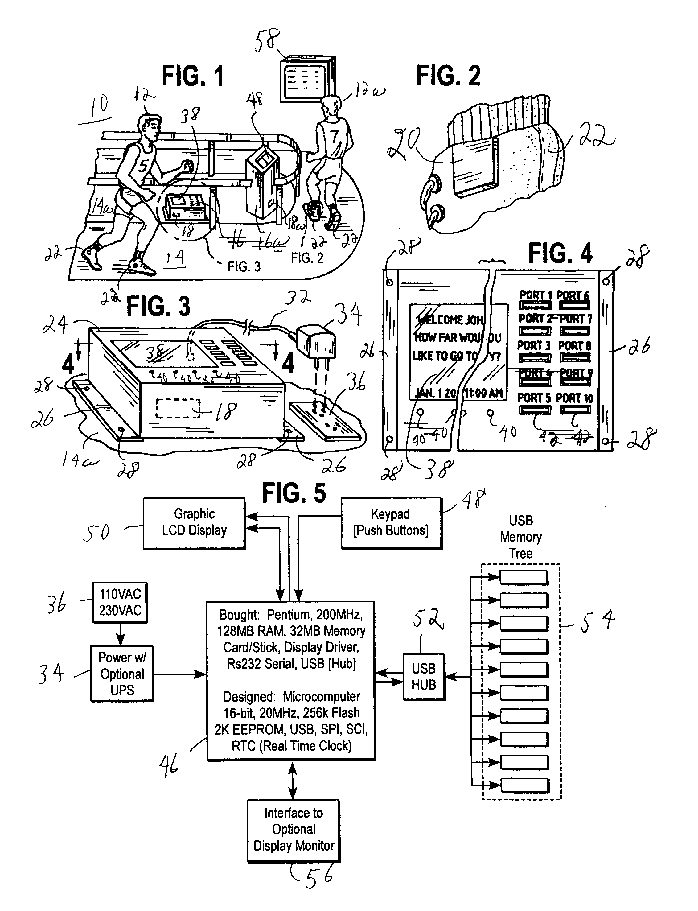
[0026]FIG. 1 shows a pictorial illustration of a lap counter system 10 for multiple runners 12 and 12a automatically counting and timing one or more of the runners 12 or 12a during their travel around a generally oval running track 14 comprising one or more electronic receivers 16 and 16a having antennas 18 and 18a, respectively, or other electronic sensing array for electrically coupling the receivers 16 and 16a to a transponder or emitter tag 20 affixed to each of the runners 12 and 12a in any suitable manner (showing an attachments to the running shoe in FIGS. 1 and 2) to relay unique information and data concerning each runner 12 and 12a ...


PUM


Abstract

A lap counter system for multiple runners automatically counts and times one or more runner(s) during a workout session exercise at either an indoor or outdoor running track suitable for use at a health club, school, business, government or other organization promoting physical activity to enhance the health of their members. The system includes standalone, computer controlled, end user friendly components that displays fitness statistics during the use of the running track for each runner without impeding the athletic activity with a cumbersome wearable device. The system preferably includes a display visible to the runner at one or more points around the track such as a scoreboard with the aforementioned statistics displayed providing the runner with a virtual coach.

Description

BACKGROUND OF THE INVENTION [0001] This invention relates to a system for counting and timing a runner on a track and, more particularly, to a system for counting and timing the laps of one or more runners on the same track without a system component impeding each individual runner or the logging of the runner's individual exercise workout session. [0002] There are a number of devices for counting and timing the laps of a runner. On personal lap counters, these devices generally fall into two different technology categories: a GPS driven device or an inertia detection device. There are significant problems and limitations with both technology categories and the respective devices used therein. First, each device shares the disadvantage of a significant investment of time to learn the operation and of money by the runner to purchase a component of these systems. [0003] Next, commercially available GPS devices are quite expensive and generally take the shape of a wristwatch or a band ...

Claims


Application Information

Patent Timeline
IPC IPC(8): A63B71/00
CPCA63B24/0021A63B69/0028A63B71/06A63B2024/0025A63B2220/836A63B2225/15A63B2225/50
Inventor KONDRAT, JAMES WALTERMIARS, CHAD LEWIS
Owner TRAKSTARR FITNESS SYST
Learn More