
Safe incineration of explosive air mixtures

Inactive Publication Date: 2006-09-28
MORRISSEY JAMES L
View PDF17 Cites 16 Cited by
  • Summary
  • Abstract
  • Description
  • Claims
  • Application Information

AI Technical Summary

Benefits of technology

[0008] An advantage of the present invention is that a system and method is provided to guard against accidental operator error and deliberate sabotage.
[0009] Another advantage of the present invention is that a system and method are provided for significant fuel savings over prior art systems.
[0010] A further advantage of the present invention is that a system and method are provided to control explosive-fume / air mixtures with a built-in safety factor through the use of the variable speed fan plus the warning message to the operator. Such gives the operator time either to correct the out of tolerance condition or to execute an orderly shut-down. Such also provides further cost savings.

Problems solved by technology

But some exhausts can be explosive if they have mixtures with the right percentages of air-to-fuel.
Such type of emergency shut-down monitoring can result in lost production time and costly cleanups and restarts.
Although this practice will work to prevent explosions, the fuel costs to incinerate the much higher flowrates resulting can be enormous.

Method used


Image

  • Safe incineration of explosive air mixtures
  • Safe incineration of explosive air mixtures
  • Safe incineration of explosive air mixtures

Examples


Embodiment Construction

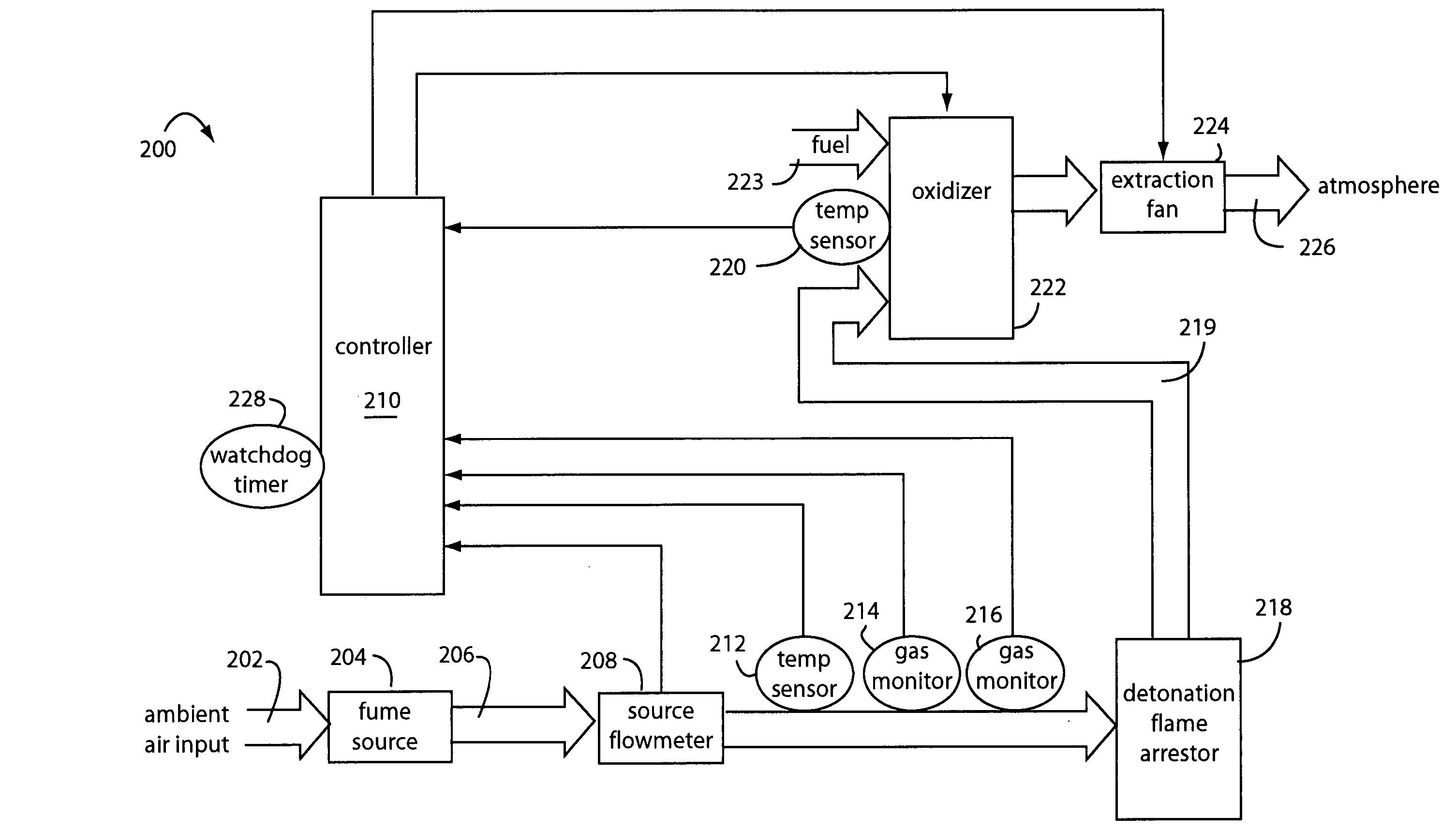
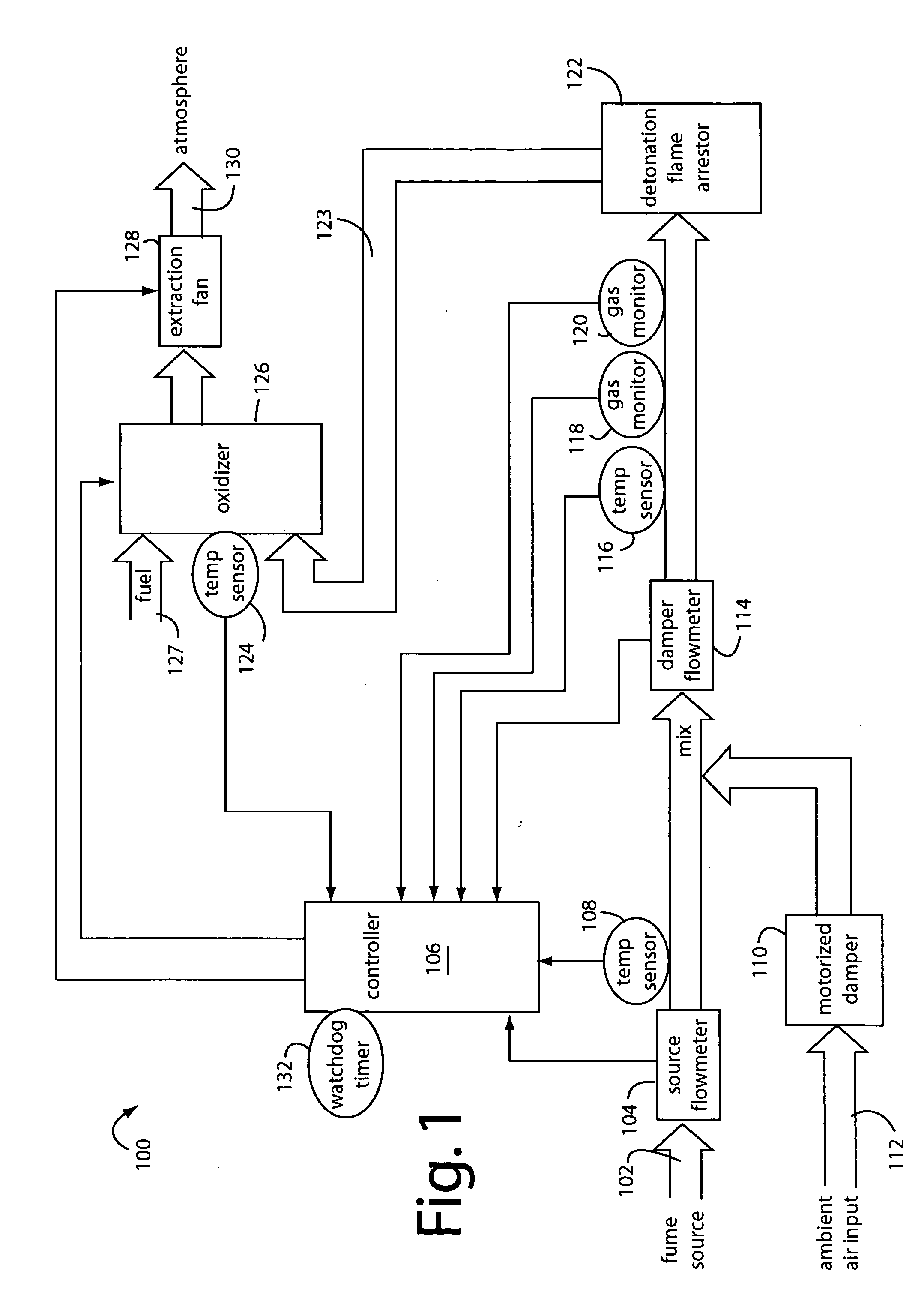
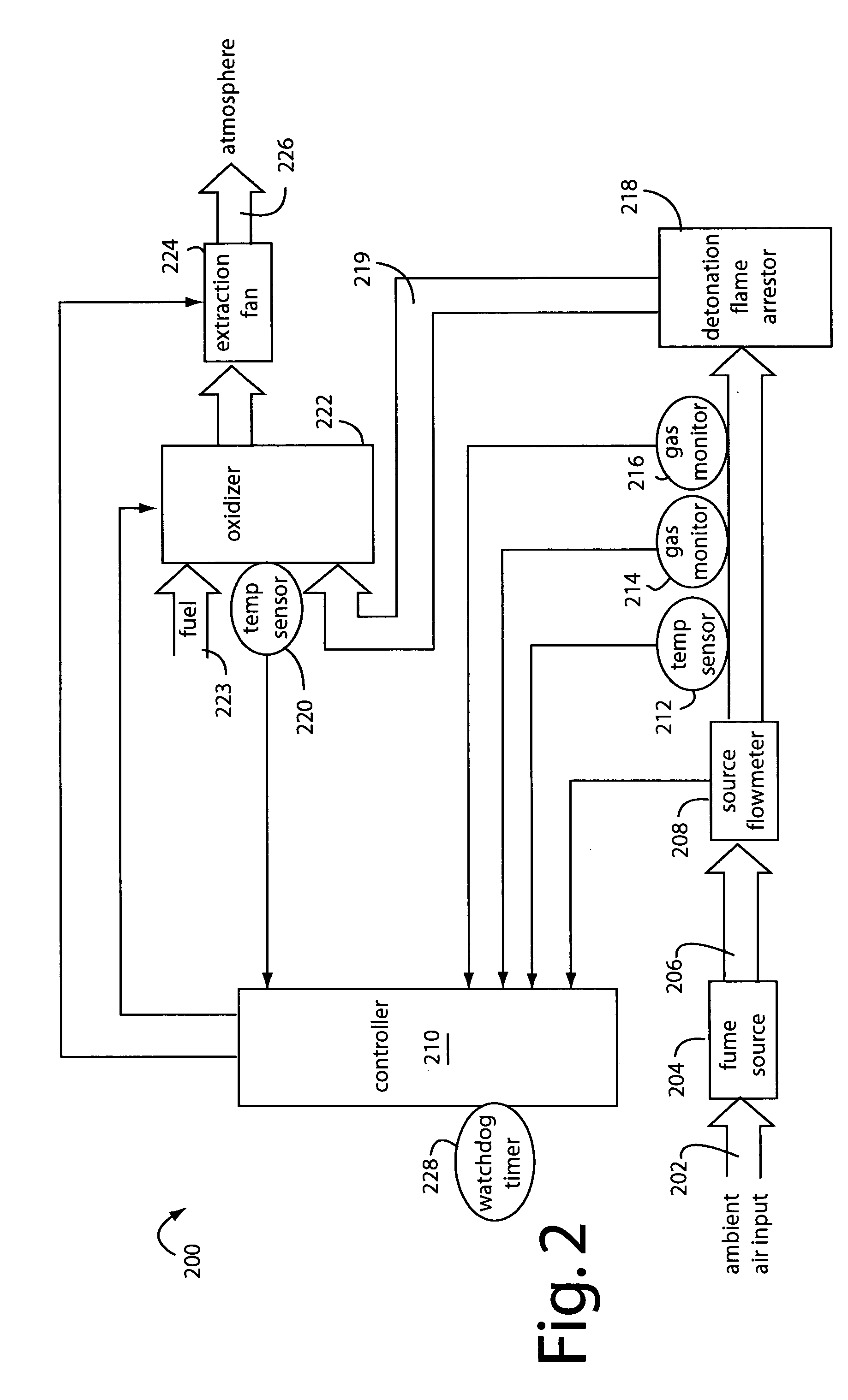
[0015]FIG. 1 illustrates a constant-source-flow fume incineration system embodiment of the present invention, and referred to by the general reference numeral 100. The system 100 is connected to receive a fume source 102 of gases for incineration before discharging them into the atmosphere. A standard flow is received from fume source 102 according to the nature of the source or government operating permits dictating such. A source flowmeter 104 monitors the volume of gases entering and reports its measurements to a system controller 106. A first temperature sensor 108 allows the controller 106 to convert to Standard Conditions for its calculations. A motorized damper 110 is adjusted by the controller 106 to admit more or less ambient air 112 in order to dilute the incoming gases enough to keep their mixture below the lower explosive limit (LEL). Such LEL is the lowest percentage of volatile gases in the air mixture that will explode if exposed to open flames or sparks, or that will...


PUM


Abstract

An explosive gas incinerator system comprises a fume source inlet for receiving a process exhaust with a volatile material that is explosive when its concentration exceeds a lower explosive limit (LEL). A source flowmeter measures the volume of process exhaust being input. A temperature sensor measures the temperature of the process exhaust. A motorized damper is used for diluting the process exhaust with an ambient air input to produce a damper outflow with an explosive concentration less than the LEL. A damper flowmeter measures the total mixture volume of the process exhaust and ambient air input in the damper outflow. Another temperature sensor measures the temperature of the damper outflow. A gas monitor measures the concentration of volatile material in the damper outflow. An oxidizer burns the damper outflow in a flame to produce a cleaner exhaust, and a fan forces gas flows through the oxidizer. A system controller is connected to receive measurement data from the flowmeters, gas monitor, and temperature sensors, and is connected to control the motorized damper to maintain the damper outflow into the oxidizer below the corresponding LEL of the volatile material. Operator errors and attempts at sabotage can be detected and controlled.

Description

FIELD OF THE INVENTION [0001] The present invention relates to exhaust gas incinerators, and more particularly to the safe incineration of explosive air mixtures. DESCRIPTION OF THE PRIOR ART [0002] Industrial processes exhaust various gases and particles into the air. Modern regulations require that the emissions be controlled and limited, and one way to scrub the exhaust is to incinerate it before it leaves the smoke stack. But some exhausts can be explosive if they have mixtures with the right percentages of air-to-fuel. The lower explosive limit (LEL) is a value that represents the minimum percent of an explosive-fume mixed in air which will explode. The source of ignition can either be an open flame or the auto-ignition temperature. [0003] Some exhausts must be licensed, certified, and monitored. The exhausts can either be permitted to be flow variable, or the more restrictive constant flow type. Thus in the manufacturing of fluorescent paint which generates formaldehyde, the f...

Claims


Application Information

Patent Timeline
IPC IPC(8): F23G7/08F23J15/00
CPCF23G5/50F23G7/06F23G7/065F23G2207/101F23G2207/30F23G2209/141F23K2401/201F23K2900/05001F23N5/242F23K2400/201
Inventor MORRISSEY, JAMES L.
Owner MORRISSEY JAMES L
Learn More