Waveform display device

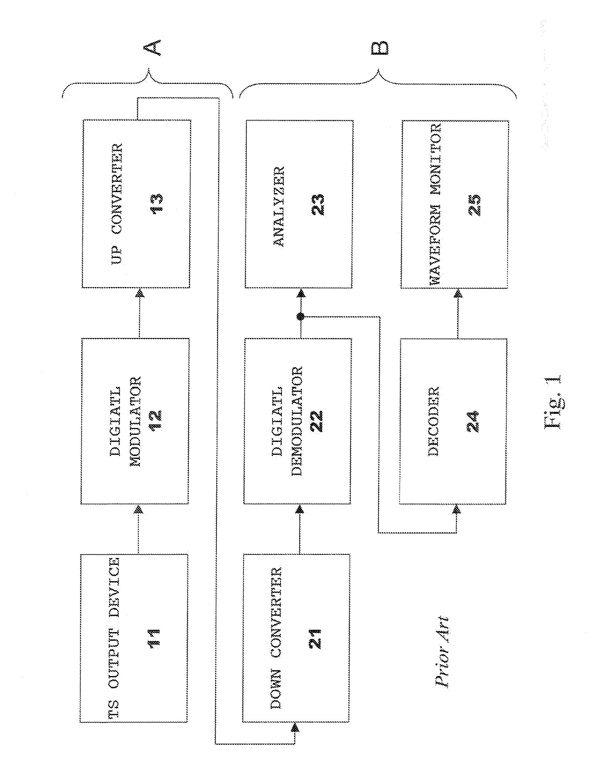
a waveform display and video signal technology, applied in signal generators with optical-mechanical scanning, color televisions with bandwidth reduction, etc., can solve the problems of user's inability to monitor the analyzer 23 cannot display the waveform of the video signal, so as to facilitate the monitoring of the transmission status and reduce the cost

Inactive Publication Date: 2006-09-28
LEADER ELECTRONICS
View PDF7 Cites 6 Cited by
  • Summary
  • Abstract
  • Description
  • Claims
  • Application Information

AI Technical Summary

Benefits of technology

[0011] An object of the present invention is to provide a waveform monitor in which the user easily monitors the transmission status and the waveform status of the compressed transmission signal.
[0018] In a waveform monitor according to the present invention, a compressed transmission signal (a TS signal, a DV stream signal, or the like) is converted not into a SDI signal but parallel data, and afterward, converted into a waveform display data. And in the waveform monitor, a transmission status of the compressed transmission signal is analyzed. Therefore, a user can monitor the transmission status and the waveform status of the compressed transmission signal by using one waveform monitor. As a result, the user is required to monitor only one display of the waveform monitor, and therefore, the user can easily monitor the transmission status and the waveform status of the compressed transmission signal.

Problems solved by technology

However, the analyzer 23 cannot display the waveform of the video signal.
Therefore, a user has not been able to monitor a waveform of the video signal by using the analyzer 23.

Method used


Image

  • Waveform display device
  • Waveform display device
  • Waveform display device

Examples


Embodiment Construction

[0031]FIG. 4 is a view for schematically explaining a flow of a video signal, for example, in a broad casting station, according to the present invention. A waveform monitor 41 of the present invention is shown in FIG. 4, instead of an analyzer 23, a decoder 24, and a waveform monitor 25 shown in FIG. 1. And, FIG. 5 is a schematic functional block diagram of the waveform monitor 41 of the present invention. Note that a device for outputting a stream may be used instead of a TS output device 11, and in this case, a DV stream signal is transmitted from a broadcasting station A in place of a TS signal. Although a case of the TS signal will be hereinafter described, a signal compressed in another format, such as the DV stream signal, may be used in place of the TS signal.

[0032] As shown in FIG. 4, in a broadcasting station B, the TS (transport stream) signal flows from a digital demodulator 22 to the waveform monitor 41. When a plurality of TS signals are decoded in the digital demodul...


PUM


Abstract

A waveform monitor comprises: means (51) for converting a compressed video signal into uncompressed parallel data; means (33) for converting the parallel data into waveform display data; means (52) for analyzing a transmission status of the compressed video signal and generating analysis data; and means (36) for displaying the waveform display data and the analysis data simultaneously. The waveform monitor can further comprise: means (31) for converting an SDI signal into parallel data; and means (32) for analyzing a transmission status of the SDI signal and generating the analysis data.

Description

BACKGROUND OF THE INVENTION [0001] The present invention relates to a device for displaying a waveform of a video signal, more specifically, to a device for displaying a waveform of a compressed video signal and analyzing a transmission status of the compressed video signal. [0002]FIG. 1 is a view for schematically explaining a flow of a video signal, for example, in a broadcasting station. As shown in FIG. 1, in a broadcasting station A, an MPEG-TS (transport stream) signal flows from, a TS output device 11 to a digital modulator 12; a TS signal digital modulated, for example, to an ISDB-T (integrated services digital broadcasting-terrestrial transmission) format flows from the digital modulator 12 to an up converter 13; and the TS signal further converted into a first predetermined frequency is transmitted from the broadcasting station A. Note that a device for outputting a DV (digital video) stream can be used instead of the TS output device 11, and in this case, the DV stream si...

Claims


Application Information

Patent Timeline
Patent Type & Authority Applications(United States)
IPC IPC(8): H04N11/04H04N11/02H04N7/12H04B1/66
CPCH04N17/004
Inventor IMAMURA, GENICHITOMITA, HIROYUKIYANO, KOJI
Owner LEADER ELECTRONICS
Why Eureka
Try Eureka