
Storage apparatus, control method and program

a technology of storage apparatus and control method, applied in the field of storage apparatus, a control method and a program, can solve the problems of no means for storing data, data writing on the medium may fail as a write fault error, no data writing means, etc., to avoid the loss of final data, accurate update, and improve the reliability of the storage apparatus

Inactive Publication Date: 2006-09-28
FUJITSU LTD
View PDF5 Cites 27 Cited by
  • Summary
  • Abstract
  • Description
  • Claims
  • Application Information

AI Technical Summary

Benefits of technology

The present invention provides a storage apparatus that can write data on a storage medium based on a write command from a higher-level apparatus. The apparatus includes a write cache control unit for storing data in a buffer memory in response to a write command, a vibration countermeasure processing unit for disabling the write cache control unit when an abnormal vibratory environment is detected. The vibration countermeasure processing unit measures the vibratory environment and determines if the abnormal vibration is likely to fail the writing process. If an abnormal vibration is detected, the vibration countermeasure processing unit disables the write cache control unit and stores the data in a temporary storage area or nonvolatile memory to prevent data loss. The temporary storage area has a larger track width for a normal storage area. The method and program of the invention ensure that data can be written accurately and reliably even in an abnormal vibration environment.

Problems solved by technology

When a vibration applied to the apparatus in such a situation increases more, the deviation amount of the head exceeds an allowable limit so that data writing on the medium may fail as a write fault error.
In such a conventional magnetic disk apparatus, when a write fault error occurs, a certain number of retries are repeated, and when error recovery is still impossible, it is considered as a medium fault to perform an alternating processing.
However, when a vibration is a factor of the write fault error, it is expected that writing failure occurs also in the case of writing into an alternating destination or writing into a system area of alternating management information storing therein information required for performing the alternating processing.
Consequently, when data cannot be finally written, there is no means for storing the data so that the data is finally lost.
However, in such a conventional magnetic disk apparatus, when the data is finally lost due to a write fault error caused by a vibration in the state where the write cache function is used, since the write command from the higher-level apparatus has been normally terminated, the error report cannot be performed so that the higher-level apparatus cannot perform retry processing for the error ending.
In other words, neither the higher-level apparatus nor the magnetic disk apparatus can recover the error and there is always a concern that data would be lost.
On the other hand, though some of the conventional magnetic disk apparatuses prohibit the writing operation when detecting an abnormal vibration by a sensor or the like, since a positional deviation due to a vibration of the head is not determined, the writing operation may be prohibited even due to a vibration which would not cause a write fault error, and since an input / output processing of the higher-level apparatus is completely prohibited during the vibration, the function of the magnetic disk apparatus is temporarily lost, and there is a problem that the processing performance is remarkably deteriorated under a vibration sensitive environment.

Method used


Image

  • Storage apparatus, control method and program
  • Storage apparatus, control method and program
  • Storage apparatus, control method and program

Examples


Embodiment Construction

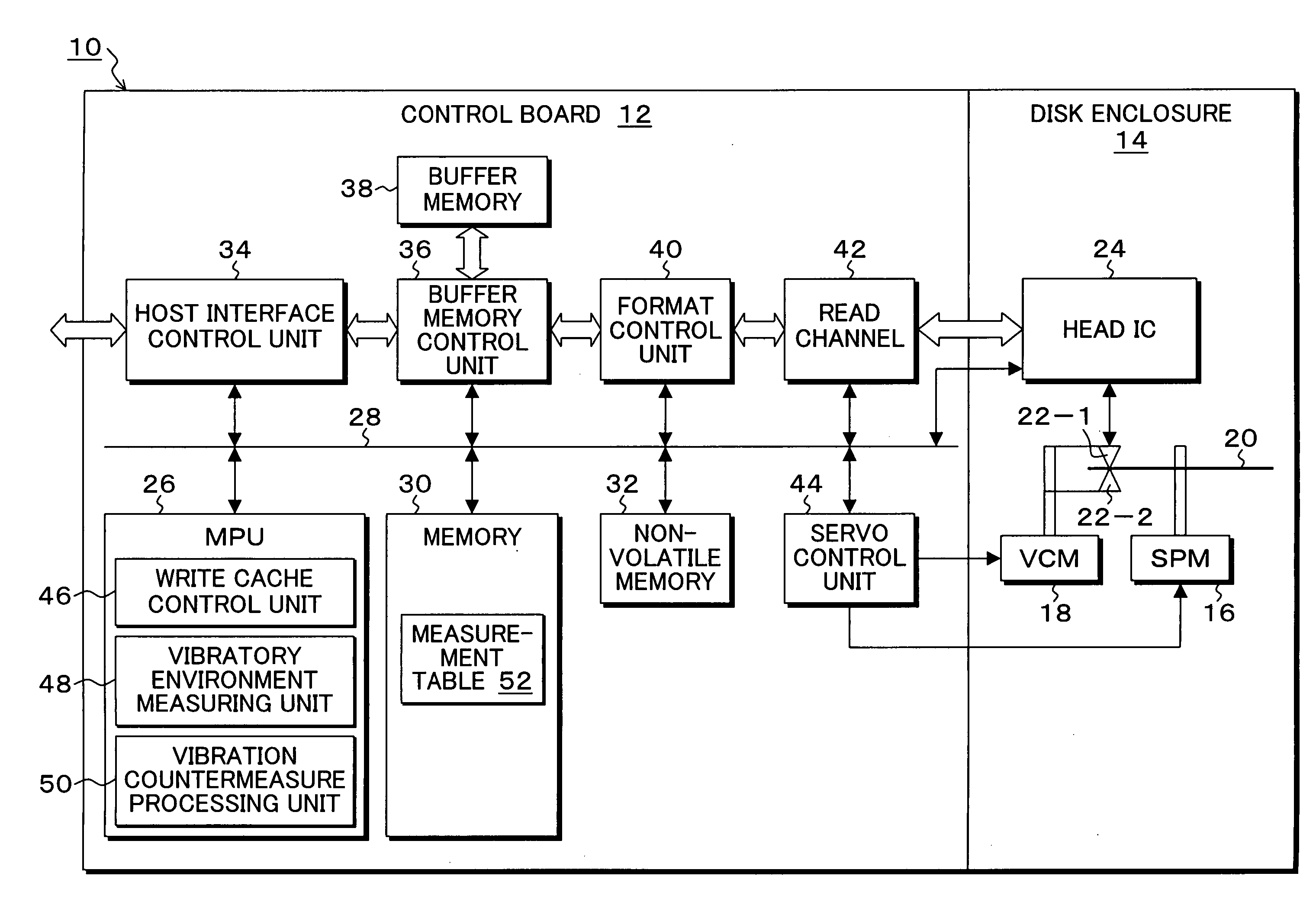
[0034]FIG. 1 is a block diagram of a magnetic disk apparatus to which the present invention is applied, which comprises a vibration countermeasure function corresponding to use situation where a write fault error may possibly occur due to an external vibration. In FIG. 1, a magnetic disk apparatus 10 known as a hard disk drive (HDD) is constituted of a disk enclosure 14 and a control board 12. The disk enclosure 14 is provided with a spindle motor 16, and a disk medium (storage medium) 20 is mounted on a rotation shaft of the spindle motor 16 and is rotated for a certain time, for example, at 4200 rpm. The disk enclosure 14 is provided with a voice coil motor 18, and the voice coil motor 18 mounts heads 22-1 and 22-2 on a tip of an arm of a head actuator to position the head relative to a recording face of the disk medium 20. A write head and a read head are integrally mounted on the heads 22-1 and 22-2. The heads 22-1 and 22-2 are connected to a head IC 24 through a signal line, an...


PUM

PropertyMeasurementUnit
thresholdaaaaaaaaaa
widthaaaaaaaaaa
storage areaaaaaaaaaaa

Abstract

The write cache control unit stores data in the buffer memory in response to a write command from a higher-level apparatus to respond a normal ending of the command, and then writes the data in the buffer memory on the disk medium. The vibratory environment measuring unit measures an environment under which a vibration is applied to the apparatus. When an abnormal vibratory environment under which writing on the disk medium likely fails is determined from a measured environment by the vibratory environment measuring unit, the vibration countermeasure processing unit disables the write cache control unit, and if the write cache data remains in the buffer memory at that time, writes the data in the temporary storage area, and if the abnormal vibratory environment is not determined, writes back the data to the original position on the disk medium.

Description

[0001] This application is a priority based on prior application No.JP 2005-088147, filed Mar. 25, 2005, in Japan. BACKGROUND OF THE INVENTION [0002] 1. Field of the Invention [0003] The present invention relates to a storage apparatus, a control method and a program for determining an abnormal vibration and avoiding a write fault error for a disk medium, and particularly to a storage apparatus, a control method and a program for controlling a write cache function in response to a write command from a higher-level apparatus and avoiding a write fault error due to an abnormal vibration. [0004] 2. Description of the Related Arts [0005] In recent years, a magnetic disk apparatus has been widely used and is used in a vehicle-mounted apparatus such as car navigation system and a home appliance such as DVD recorder. Further, the magnetic disk apparatus has been made smaller so that a track itself recording therein data is made finer and a track interval is made narrower. In such a situati...

Claims


Application Information

Patent Timeline
Patent Type & Authority Applications(United States)
IPC IPC(8): G11B21/02
CPCG11B5/5582G11B19/04
Inventor YOSHIDA, OSAMUMOTOKI, MASAAKIKAKUYA, TAKUMITSURUOKA, MASAKAZUKASHIWAGI, GOICHIOBUCHI, MASAKIAOKI, SHUNSUKE
Owner FUJITSU LTD
Learn More