
Backlight Module of LCD Device

a backlight module and lcd technology, applied in non-linear optics, instruments, optics, etc., can solve the problems of reducing affecting the brightness so as to improve the brightness and brightness uniformity and reduce the thickness of the backlight module

Inactive Publication Date: 2006-09-28
HANNSTAR DISPLAY CORPORATION
View PDF4 Cites 70 Cited by
  • Summary
  • Abstract
  • Description
  • Claims
  • Application Information

AI Technical Summary

Benefits of technology

[0012] It is an advantage of the present invention that the mura will not occur in the backlight module of the present invention. Additionally, the brightness and the brightness uniformity of the backlight module are improved and the thickness of the backlight module is reduced.
[0013] These and other objectives of the present invention will no doubt become obvious to those of ordinary skill in the art after reading the following detailed description of the preferred embodiment that is illustrated in the various figures and drawings.

Problems solved by technology

CRTs are characterized by large depth dimensions, undesirable weight, and fragility.
However, the CCFL consists of mercury (Hg), which is an environmental pollutant.
In some prior art, two diffuser plates are used to achieve the good mixing of red, green, and blue light, but this technique decreases the brightness of the backlight module.
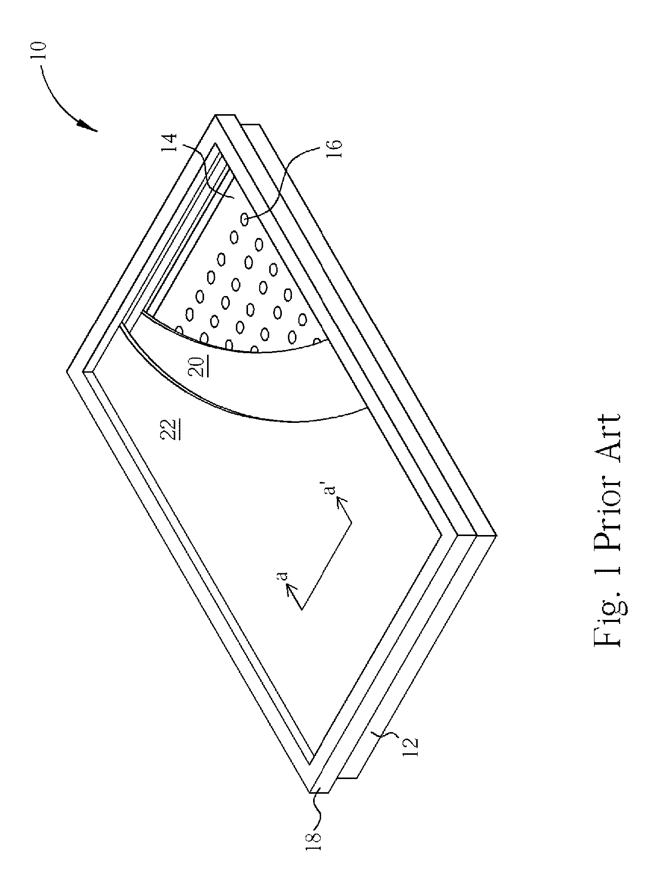
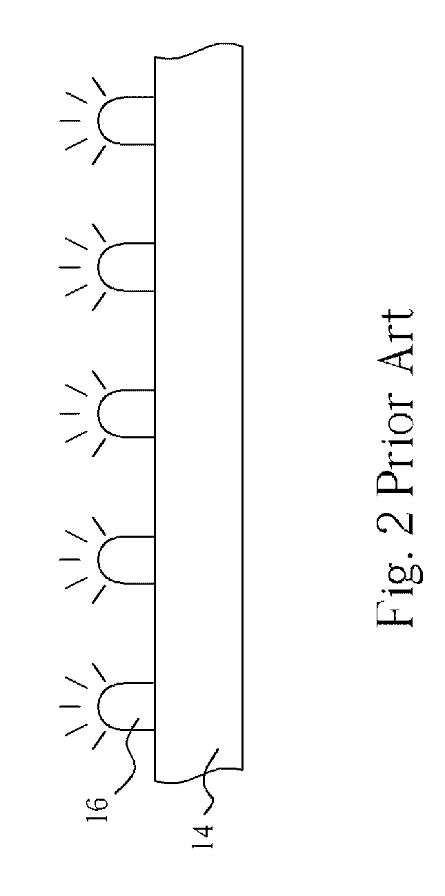
Furthermore, the brightness uniformity of the LED direct type backlight module 10 of the prior art is bad and an LED mura will occur.

Method used


Image

  • Backlight Module of LCD Device
  • Backlight Module of LCD Device
  • Backlight Module of LCD Device

Examples


Embodiment Construction

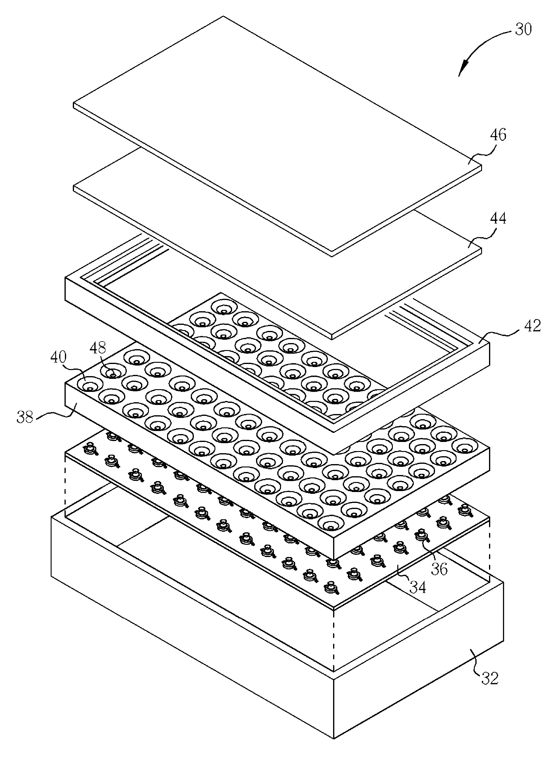
[0020] Please refer to FIG. 3. FIG. 3 is an exploded perspective diagram illustrating a backlight module 30 of an LCD device according to a first preferred embodiment of the present invention. As shown in FIG. 3, a backlight module 30 of an LCD device includes a back-up structure 32, a printed circuit board 34, a plurality of point light source generators 36 disposed on the printed circuit board 34, a reflection sheet 38, which has a plurality of fillisters 40 formed in the reflection sheet 38, a front cover 42, at least one diffuser plate 44, and at least one optical film 46. The reflection sheet 38 is fabricated by plastic injection-molding or metal injection-molding and each of the fillisters 40 has an opening 48 in the bottom of the fillisters 40. Furthermore, the fillisters 40 are arranged as an orthogonal matrix. However, the arrangement of the fillister shape reflectors 40 is not restricted to be an orthogonal matrix, and other arrangements may be applied according to the des...


PUM

PropertyMeasurementUnit
angleaaaaaaaaaa
reflectionaaaaaaaaaa
shapeaaaaaaaaaa

Abstract

A backlight module of an LCD device includes a plurality of fillisters formed in a reflection sheet and each of the fillisters having a reflection surface and a symmetrical axis. A plurality of point light source generators set in the fillisters, in which lights generated by the point light source generators are reflected by the reflection surfaces of the fillisters and the reflection sheet, and a profile of the point light source generators determines a shape of the fillisters. At least one diffuser plate installed on the reflection sheet for scattering the lights generated by the point light source generators and reflected by the reflection surfaces of the fillisters and the reflection sheet, in which an air space is formed between the diffuser plate and the reflection sheet.

Description

BACKGROUND OF INVENTION [0001] 1. Field of the Invention [0002] The present invention relates to a backlight module of an LCD device, and more particularly, to a backlight module of an LCD device, which utilizes a plurality of point light source generators as light sources and has a reduced thickness and improved optical performance. [0003] 2. Description of the Prior Art [0004] Liquid Crystal Displays (LCDs) are widely used in digital cameras, Personal Digital Assistants (PDAs), computer monitors, and flat panel televisions where the elimination of cathode ray tube (CRT) technology is desirable for several reasons. CRTs are characterized by large depth dimensions, undesirable weight, and fragility. Additionally, CRTs require a relatively high voltage power supply in order to sufficiently accelerate electron beams for displaying images. [0005] In general, LCD devices have many advantages over CRT display devices in that they are thin and low in power consumption, etc. Therefore, LCD...

Claims


Application Information

Patent Timeline
Patent Type & Authority Applications(United States)
IPC IPC(8): G02F1/1335H01L33/00H01L33/60
CPCG02F1/133603G02F1/133605G02F1/133611
Inventor HUANG, CHI-JENCHANG, CHIH-LI
Owner HANNSTAR DISPLAY CORPORATION
Learn More