
Abnormality detector of moving robot

a moving robot and abnormality detection technology, applied in the direction of electrical programme control, program control, instruments, etc., can solve the problems of robot prone to tipping, general susceptible to malfunction, and prone to damage of communication interface, so as to improve the reliability of abnormality detection of the mobile robot, and improve the reliability of abnormality detection.

Inactive Publication Date: 2006-09-28
HONDA MOTOR CO LTD
View PDF6 Cites 31 Cited by
  • Summary
  • Abstract
  • Description
  • Claims
  • Application Information

AI Technical Summary

Benefits of technology

[0005] An object of this invention is therefore to overcome the foregoing problems by providing an abnormality detection system of a mobile robot, which is configured to self-diagnose whether or not an abnormality has occurred and, when an abnormality is detected, to store the diagnostic result in the memory of an onboard computer while also outputting it to an external computer for storage in a memory thereof, thereby improving the reliability of abnormality detection.
[0006] Another object of this invention is to provide an abnormality detection system of a mobile robot whose abnormality detection reliability is further improved by, when an abnormality or the like is detected, also storing the time of occurrence and / or the quantity of state including the posture and the like at the time.
[0007] In order to solve the aforesaid objects, this invention provides, as recited in claim 1 mentioned below, a system for detecting abnormality of a mobile robot having at least a drive motor, an internal sensor that senses a quantity of state of the internal of the robot and a control unit constituted by an onboard microcomputer that operates the drive motor based on the quantity of state obtained from an output of the internal sensor to move, the control unit comprising: self-diagnosis means for self-diagnosing whether the quantity of state is an abnormal value, or whether at least one of onboard equipments mounted on the robot including at least the drive motor and the internal sensor is abnormal; abnormality information outputting means for outputting, when an abnormality is self-diagnosed by the self-diagnosis means, information of the abnormality affixed with a time on which the abnormality occurred; and abnormality information storing means for storing the output of the abnormality information outputting means in an internal memory provided in the control unit and in an external memory provided outside the robot. Thus, since it is configured such that it is self-diagnosed whether the quantity of state is an abnormal value, or whether at least one of the internal sensor, etc., is abnormal and when an abnormality is self-diagnosed, abnormality information affixed with a time on which the abnormality occurred is outputted to be stored in an internal memory and in an external memory, it becomes possible to improve the reliability of abnormality detection of the mobile robot. Further, by storing the information affixed with a time on which the abnormality occurred, it becomes possible to ascertain accurately the course of events leading up to the abnormality. It should be noted that, in this specification, “abnormality” means whole cases other than normal, which are non-normal conditions due to any events including deterioration, failure and damages.

Problems solved by technology

A communications interface is generally susceptible to malfunctioning.
Moreover, since the posture of a legged mobile robot, particularly a biped humanoid mobile robot, is unstable, the robot is apt to tip over when an abnormality arises within the system, and the communications interface is liable to be damaged as a result.
When the communications interface fails, the probability of the self-diagnosis result being lost becomes high.
However, the aforesaid prior art is not altogether satisfactory on these points.

Method used


Image

  • Abnormality detector of moving robot
  • Abnormality detector of moving robot
  • Abnormality detector of moving robot

Examples


Embodiment Construction

[0030] An abnormality detection system of a mobile robot according to an embodiment of this invention will be explained with reference to the attached drawings in the following.

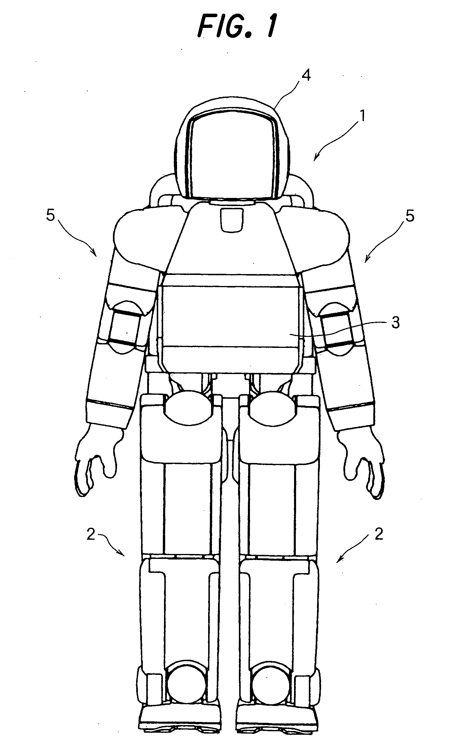
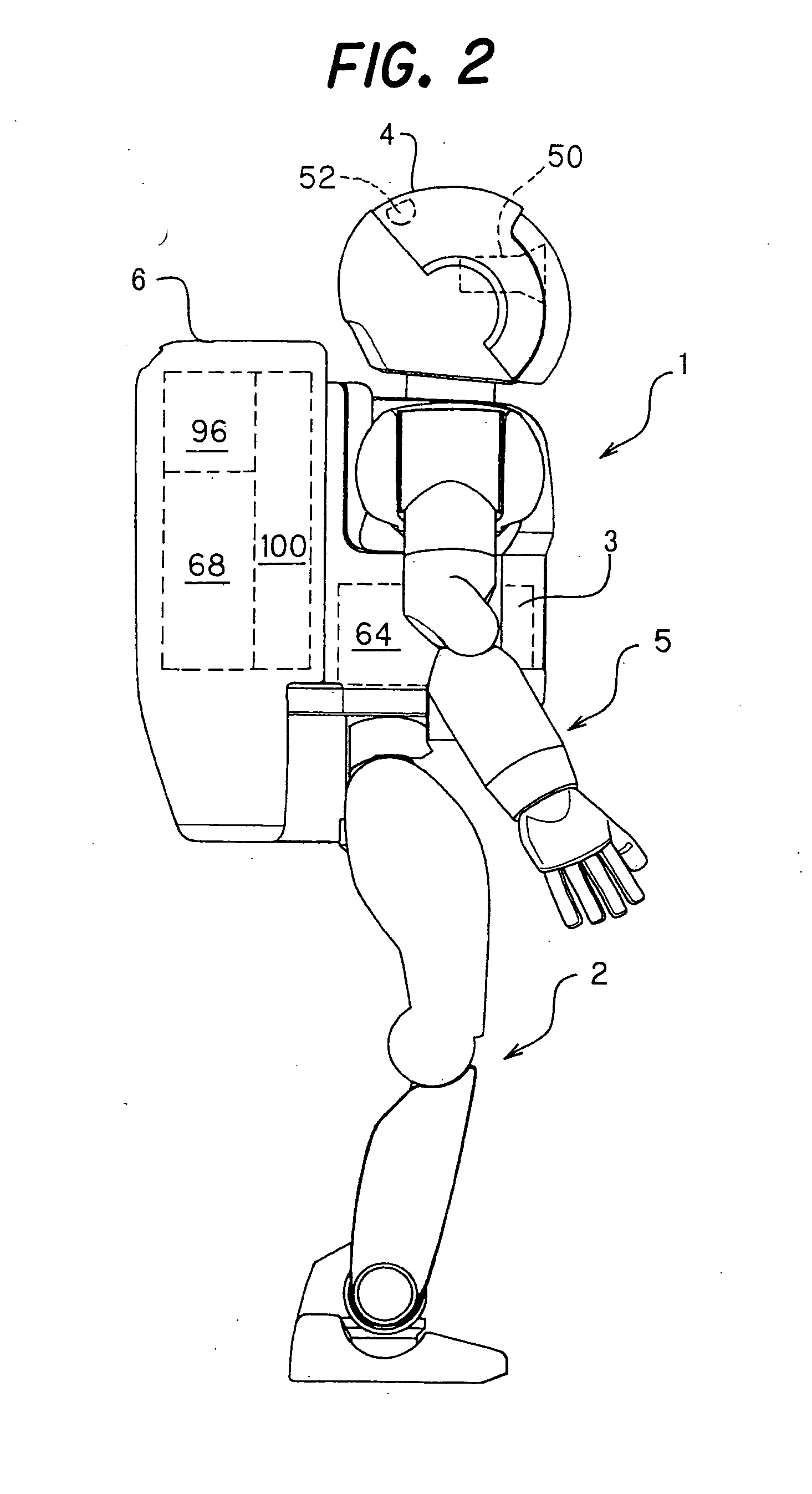
[0031]FIG. 1 is a front view of a mobile robot, specifically a legged mobile robot, to which an abnormality detection system of a mobile robot according to an embodiment of this invention applies, and FIG. 2 is a side view thereof. A biped humanoid robot is taken here as an example of a legged mobile robot.

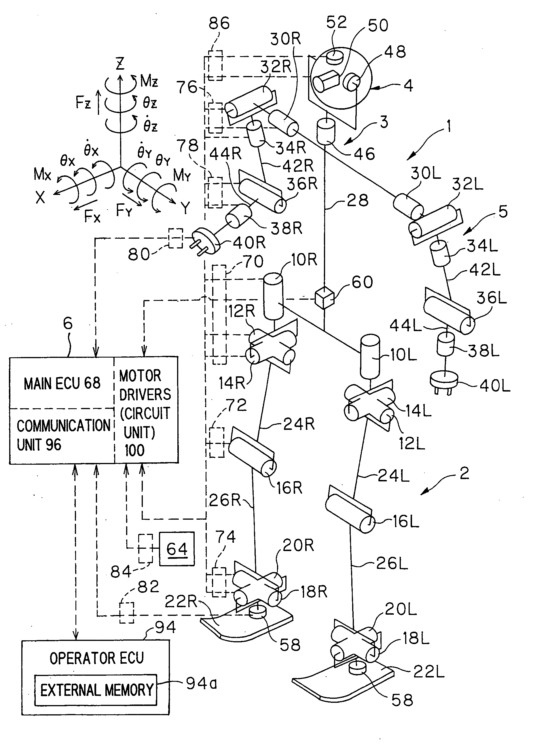
[0032] As shown in FIG. 1, the legged mobile robot (hereinafter called simply “robot”) 1 is equipped with a plurality of, more specifically two leg linkages 2 and a body (main unit) 3 above the leg linkages 2. A head 4 is formed above the body 3 and two arm linkages 5 are connected one to either side of the body 3. As shown in FIG. 2, a housing unit 6 is mounted on the back of the body 3 for accommodating therein, inter alia, a control unit (explained later). The robot 1 shown in FIGS. 1 and 2 is equipped...


PUM


Abstract

In an abnormality detection system of a mobile robot, it is configured such that it is self-diagnosed whether the quantity of state is an abnormal value, or whether at least one of the internal sensor, etc., is abnormal and when an abnormality is self-diagnosed, abnormality information affixed with a time on which the abnormality occurred is outputted to be stored in an internal memory and in an external memory. With this, it becomes possible to improve the reliability of abnormality detection of the mobile robot and by storing the information affixed with a time on which the abnormality occurred, it becomes possible to ascertain accurately the course of events leading up to the abnormality. It is further configured such that in addition to a time on which the abnormality occurred, the information is stored in an external memory together with a parameter indicative of the quantity of state.

Description

TECHNICAL FIELD [0001] This invention relates to an abnormality detection system of a mobile robot. BACKGROUND ART [0002] As an abnormality detection system of a mobile robot such as a legged mobile robot, there is known the technology taught by Japanese Laid-open Patent Application No. 2001-150374. This system diagnoses itself for abnormalities and informs the user (operator) of the result of the diagnosis by voice via an audio output device and a communications interface, in a natural conversational manner. [0003] A communications interface is generally susceptible to malfunctioning. Moreover, since the posture of a legged mobile robot, particularly a biped humanoid mobile robot, is unstable, the robot is apt to tip over when an abnormality arises within the system, and the communications interface is liable to be damaged as a result. When the communications interface fails, the probability of the self-diagnosis result being lost becomes high. [0004] In addition, it is convenient ...

Claims


Application Information

Patent Timeline
Patent Type & Authority Applications(United States)
IPC IPC(8): B25J5/00A63H11/18B25J9/16B25J13/00B25J19/06
CPCB25J9/1674G05B2219/34454G05B2219/34455G05B2219/42268
Inventor OGAWA, NAOHIDEAIHARA, MASAKIMATSUMOTO, TAKASHI
Owner HONDA MOTOR CO LTD
Learn More