
Apparatus and method for measuring supporting force of large diameter ferroconcrete piles

a technology of supporting force and ferroconcrete, which is applied in the direction of mechanical measuring arrangement, instruments, and using mechanical means, etc., can solve the problems of consuming a considerable amount of natural resources, affecting the entire construction, and being impossible for a designer to avoid

Active Publication Date: 2006-09-28
G TECH CO LTD A ORGANIZED UNDER THE LAWS OF THE REPUBLIC OF KOREA +2
View PDF1 Cites 48 Cited by
  • Summary
  • Abstract
  • Description
  • Claims
  • Application Information

AI Technical Summary

Benefits of technology

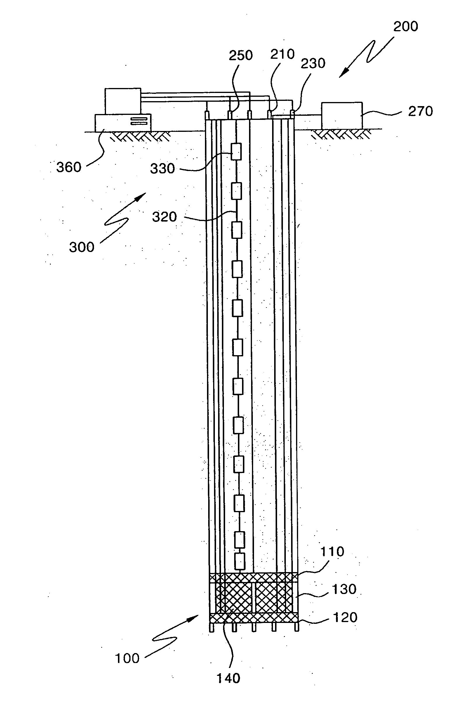
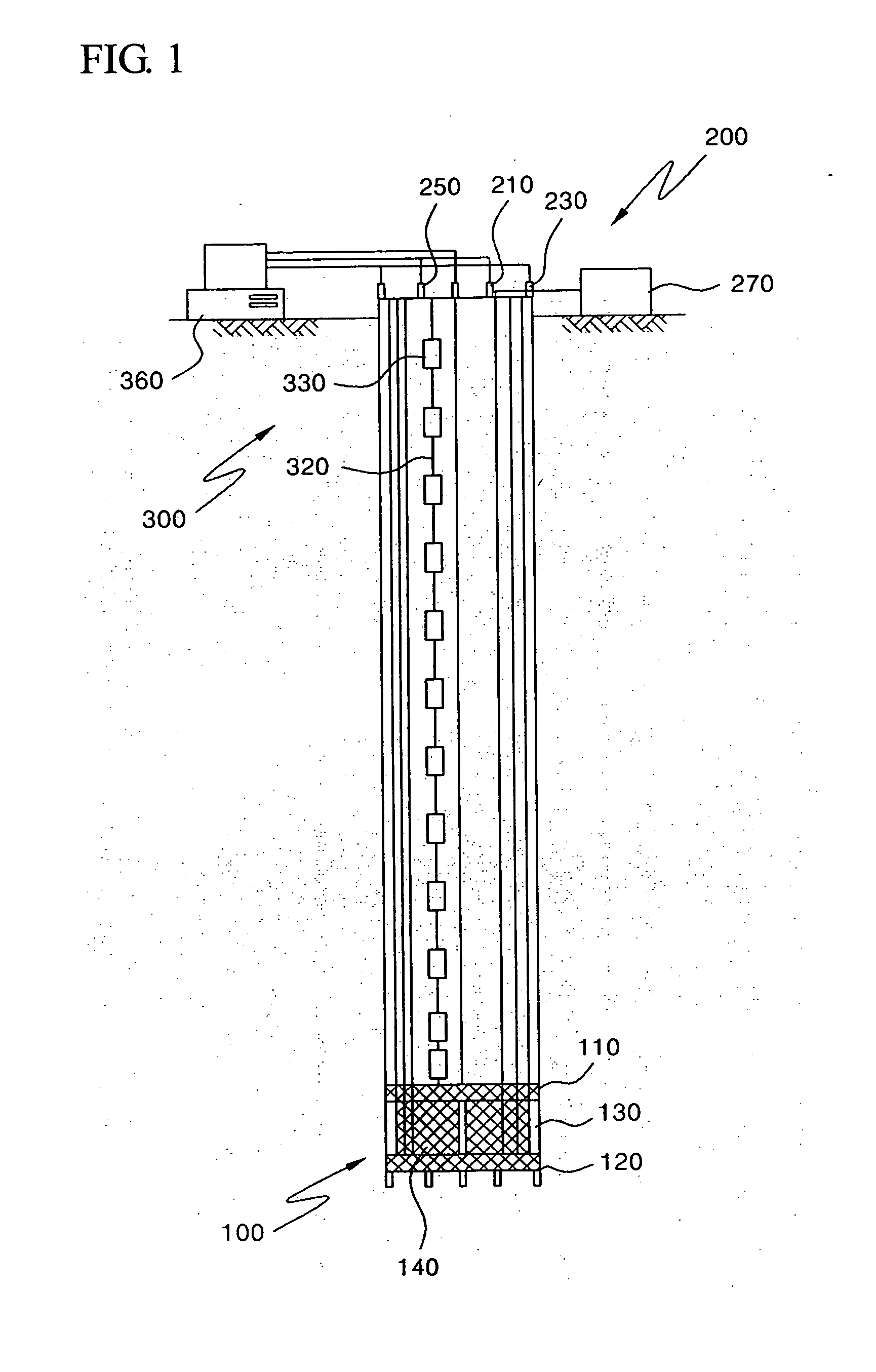
[0020] Accordingly, it is a primary object of this invention to provide an apparatus for measuring a supporting force of large diameter ferroconcrete piles installed at a scene by means of a bi-directional front end oil pressure loading apparatus using a high pressure loading system capable of reducing the number of oil pressure cylinders required for a predetermined loading capacity, thereby solving problems relating to arrangement of oil pressure cylinders and adjustment of low oil pressure supplied to a respective oil pressure cylinder.
[0021] An additional object of this invention is to provide an apparatus for measuring a supporting force of large diameter ferroconcrete piles installed at a scene by means of a bi-directional front end oil pressure loading apparatus using a high pressure loading system capable of having a high loading capacity and an economic manufacturing cost, and capable of obtaining protection from eccentricity in loading and working convenience with adjustment of a hollowed diameter, and capable of being applied to middle and small diameter piles installed at the scene, and loading closed piles and buried piles, in addition to the large diameter piles installed at the scene.
[0024] A further object of this invention is to provide an apparatus for measuring a supporting force of large diameter ferroconcrete piles installed at a scene by means of a bi-directional front end oil pressure loading apparatus using a high pressure loading system having a displacement measuring rod capable of reducing weight using stainless materials and conveniently adhering by means of a one-touch connection method.

Problems solved by technology

In the above described static post loading test, however, methods of establishing pressurization and a reaction system and a spacious test lot are required for the purpose of applying a load, resulting in many requirements such as air conditioning, maintenance of the condition of the scene, and the like.
In addition, if the supporting force is smaller than a required value due to an operational defect because a load to be imposed on one post is very heavy, the entire construction can be adversely affected in view of utility and stability of a large diameter post.
Therefore, it is impossible for a designer to avoid implementing a conservative layout when a load is used and laid out with its value assumed and tolerated on the basis of ground conditions, thereby amounting to a considerable consumption of a natural resource.
As a result, it takes a long time to measure a supporting load.
Accordingly, concrete piles to be used in a laboratory experiment are different from those used in a working environment in view of front end supporting force and column face abrasion, which results in a problem in terms of degraded reliability in such an apparatus for measuring a supporting load using an Osterberg cell.
In addition, such an apparatus for measuring a supporting load using an Osterberg cell has a flaw in that only a load for supporting non-iron concrete piles can be measured, whereas the concrete piles utilized at a working scene are concrete piles with iron built in.
Such an apparatus for measuring a supporting load has deficiency in that the size of basis piles is limited and the number of oil pressure cylinders is unlimited, with the result that such an apparatus is not adopted for a necessary loading capacity.
In addition, the increased number of oil pressure cylinders makes it difficult to equally adjust oil amount, and therefore it is difficult to accurately adjust a load to be tested.

Method used


Image

  • Apparatus and method for measuring supporting force of large diameter ferroconcrete piles
  • Apparatus and method for measuring supporting force of large diameter ferroconcrete piles
  • Apparatus and method for measuring supporting force of large diameter ferroconcrete piles

Examples


example 1

[0094]FIG. 9 is a schematic view showing bi-directional pile loading test equipment using a double-action hollowed high-pressure jack according to this invention, FIG. 10 is a front view of FIG. 9, FIG. 11 is a plan view of FIG. 9, FIG. 12 is a cross-section view showing establishment of a double-action hollowed high-pressure jack at the exterior of the front end of open steel tube piles according to this invention, FIG. 13 is a cross-section view showing establishment of a double-action hollowed high-pressure jack at the interior of the front end of open steel tube piles according to this invention, FIG. 14 is a cross-section view showing establishment of a shoe at the front end of open steel tube piles after a double-action hollowed high-pressure jack is installed at the interior of the front end according to this invention, FIG. 15 is a cross-section view showing establishment of a double-action hollowed high-pressure jack at the exterior of the front end of closed steel tube pil...

example 2

[0103]FIG. 17 is a schematic view showing bi-directional test equipment using a spring restoration type single-action oil pressure jack according to this invention, FIG. 18 is a front view showing a spring restoration type single-action oil pressure jack according to this invention, FIG. 19 is a cross-section view showing the internal structure of a spring restoration type single-action oil pressure jack according to this invention, and FIG. 20A and FIG. 20B are exemplary views showing a state in which a stroke of the oil pressure jack after completion of a bi-directional piles loading test is restored by means of a spring elastic force installed on its interior according to this invention.

[0104] As shown in these drawings, bi-directional piles loading test equipment using a spring restoration type single-action oil pressure jack according to this invention comprises: an upper disc 110 having a predetermined thickness and diameter; a lower disc 120 positioned below the upper disc 1...

example 3

[0109]FIG. 8 A is a graph showing an abrasion distribution chart at a column face with every step of a measured load in the case that a loading apparatus 100 is installed at the front end of piles, FIG. 8 B is a graph showing a front end load, FIG. 8 C is a graph showing an abrasion distribution chart at a column face with every step of a measured load changed in the case of head loading, and FIG. 8 D is a graph showing an axis load distribution chart.

[0110] Hereinafter, a method for writing the axis load distribution chart when a loading apparatus 100 is installed at the front end of piles will be explained.

[0111] The method for writing the axis load distribution chart comprises a first step of measuring values from an axis load measuring sensor with every loading step.

[0112] A second step calculates a piles column face abrasion at a predetermined loading step using the measured values, writes a distribution chart according to its depth.

[0113] At this point, a column face abras...


PUM


Abstract

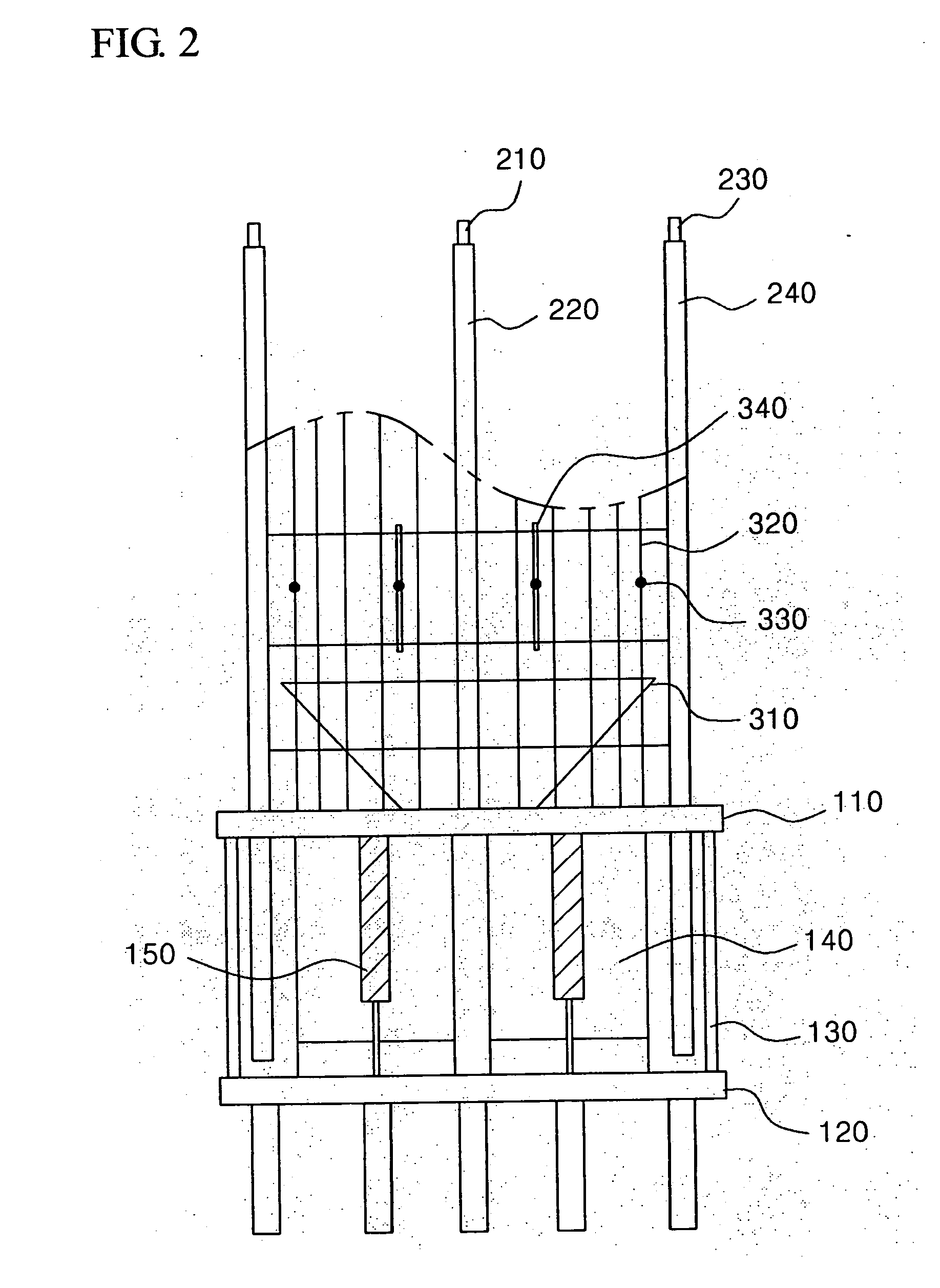
An apparatus measures a supporting force of ferroconcrete piles by means of a bi-directional front end oil pressure loading apparatus using a high pressure loading system capable of measuring a supporting force, a sinking amount and an axis load distribution on the ferroconcrete piles. The apparatus comprises: a steel plate having a predetermined thickness and diameter and including upper and lower discs having penetration holes through which concrete passes; a fixing member for separating the discs from each other by a predetermined distance; a high oil pressure cylinder for producing an oil pressure force; an oil cylinder inflation displacement measuring sensor for measuring a displacement; an upper displacement measuring rod coupled to the upper disc for measuring a displacement of the upper disc; a lower displacement measuring rod coupled to the upper disc for measuring a displacement of the lower disc; an axis load transition measuring instrument including a tremie induction tube coupled to the upper disc for guiding concrete to the penetration holes; iron elements coupled to the upper disc; a load sensor for measuring ground abrasion; and a sensor line for transferring a signal and current to the load sensor. A corresponding method is disclosed.

Description

CLAIMS OF PRIORITY [0001] This application makes reference to, incorporates the same herein, and claims all benefits accruing under 35 U.S.C. §119 from applications entitled APPARATUS FOR MEASURING SUPPORTING FORCE OF LARGE DIAMETER FERROCONCRETE PILES INSTALLED ON SCENE BY MEANS OF BI-DIRECTIONAL FRONT END OIL PRESSURE LOADING APPARATUS USING HIGH-PRESSURE LOADING SYSTEM AND METHOD THEREOF, earlier filed in the Korean Intellectual Property Office on 25 Mar. 2005 and 23 June 2005 and there, duly assigned Serial Nos. 10-2005-0024741 and 10-2005-0054235, respectively, and applications bearing the aforesaid title of the invention, earlier filed in the Korean Intellectual Property Office on 15 Nov. 2005 and there, duly assigned Serial Nos. 10-2005-0109369 and 10-2005-109370. BACKGROUND OF THE INVENTION [0002] 1. Technical Field [0003] This invention relates to an apparatus and method for measuring a supporting force of large diameter ferroconcrete piles installed at a scene by means of ...

Claims


Application Information

Patent Timeline
IPC IPC(8): E02D5/00
CPCE02D33/00
Inventor CHOI, YONG-KYULEE, MIN-HEE
Owner G TECH CO LTD A ORGANIZED UNDER THE LAWS OF THE REPUBLIC OF KOREA
Learn More