Printer having a platen

a platen and printing technology, applied in the field of printing, can solve the problems of low print quality, drop in print quality, and unclear printing

Active Publication Date: 2006-09-21
TOSHIBA TEC KK
View PDF14 Cites 6 Cited by
  • Summary
  • Abstract
  • Description
  • Claims
  • Application Information

AI Technical Summary

Benefits of technology

[0013] In order to attain the above object, a printer according to an embodiment of the present invention comprises a print head and a platen. The print head is linearly moved along a print medium to print the print medium. The platen supports the print medium, and is located opposite to the print head. The platen includes a first end portion, a second end portion and an intermediate portion, and is formed of material having stiffness. The first and second end portions are located at respective ends of the platen in the moving direction of the print head. The intermediate portion is located between the first and second end portions. The first and second end portions are supported by spring members such that they can be elastically displaced in the moving direction of the platen toward or away from the print head. The intermediate portion is formed to be more easily warped than the first and second end portions.

Problems solved by technology

Inevitably, the print quality is low.
Consequently, printing is unclear, and the print quality drops.

Method used


Image

  • Printer having a platen
  • Printer having a platen
  • Printer having a platen

Examples


Embodiment Construction

[0029] An embodiment of the present invention will be explained with reference to FIGS. 1 to 12.

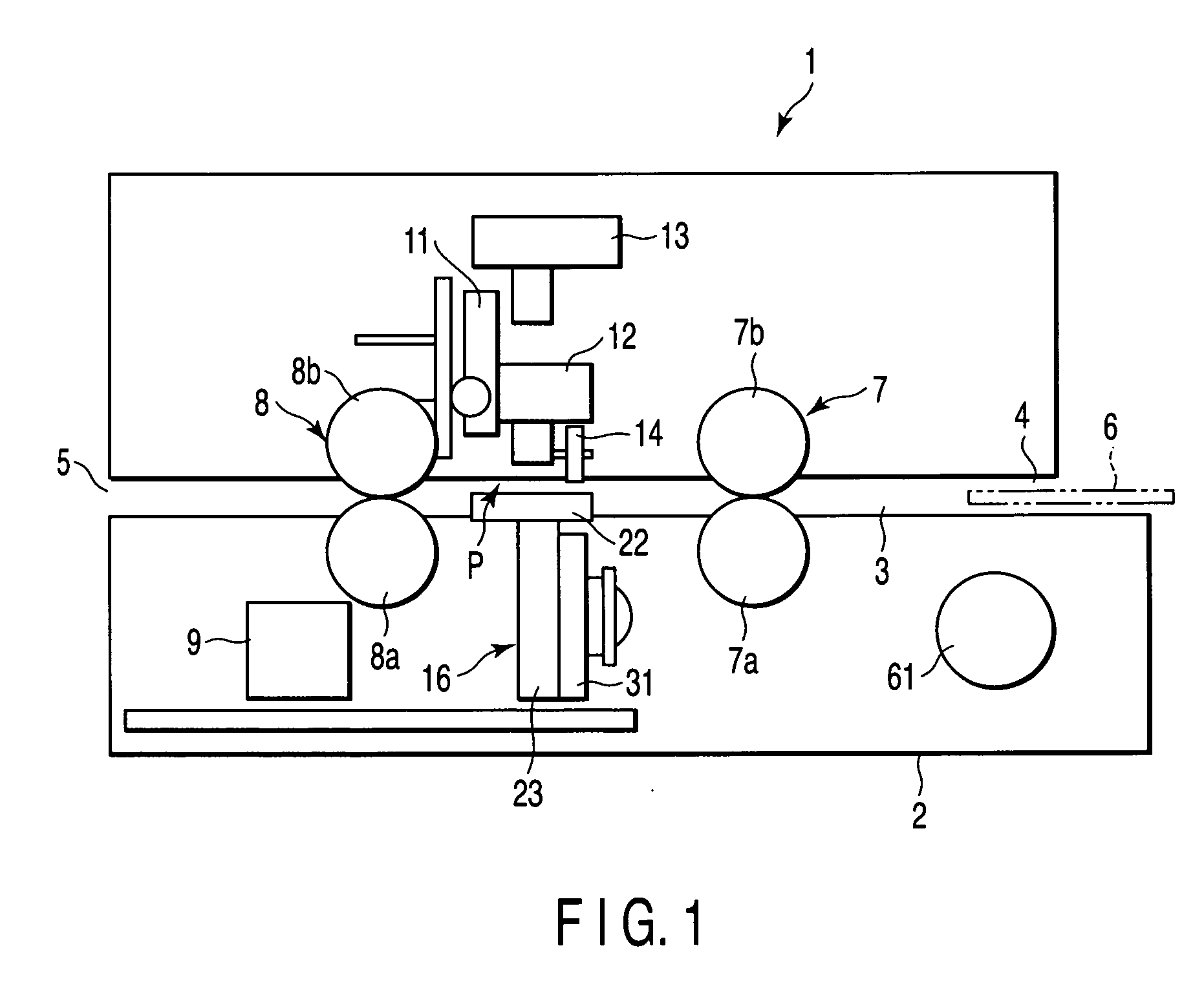
[0030]FIG. 1 schematically shows the structure of an impact printer 1 by way of example. The impact printer 1 is provided with an apparatus body 2. In the apparatus body 2, a transfer path 3 is provided to transfer a print medium. An upstream end of the transfer path 3 communicates with an insertion slot 4 provided in the apparatus body 2. A downstream end of the transfer path 3 communicates with an ejection slot 5 provided in the apparatus body 2.

[0031] In this embodiment, a passbook 6 is used as the print medium. The passbook 6 is inserted into the transfer path 3 through the insertion slot 4, while it is open. As shown in FIG. 10, the passbook 6 includes a print region 6a and a stepped portion 6b. The print region 6a is provided to extend between the left-hand page and right-hand page of the passbook 6. The stepped portion 6b extends at the center of the print region 6a in a directio...


PUM


Abstract

A printer includes a print head for printing on a print medium and a platen which supports the print medium, and is located opposite to the print head. The print head is linearly moved along the print medium. The platen includes first and second end portions and an intermediate portion, and is formed of material having stiffness. The first and second end portions are located at respective ends of the platen in the moving direction of the print head, and the intermediate portion is located between the first and second end portions. The first and second end portions are supported by respective spring members, such that they can be elastically displaced in a direction toward or away from the print head. The intermediate portion is formed to be more easily warped than the first and second end portions.

Description

BACKGROUND OF THE INVENTION [0001] 1. Field of the Invention [0002] The present invention relates to a printer provided with an impact type print head and a platen located opposite to the print head. To be more specific, the invention relates to the structure of a platen which receives an impact from a print head at the time of printing on a print medium. [0003] 2. Description of the Related Art [0004] For example, an impact type printer comprises a print head which is linearly moved over a print medium, and a platen which supports the print medium. The print head has a number of wires projecting toward the print medium. When the wires hit an ink ribbon upon the print medium, characters, marks or the like are printed on the print medium. The platen extends in the moving direction of the print head, and is located opposite to the print head with respect to the print medium. The platen is hit by the wires of the print head at the time of printing on the print medium. Thus, the platen ...

Claims


Application Information

Patent Timeline
Patent Type & Authority Applications(United States)
IPC IPC(8): B41J11/08B41J11/02
CPCB41J3/283
Inventor SANADA, TSUYOSHINIHASHI, KIYOTAKA
Owner TOSHIBA TEC KK
Why Eureka
Try Eureka