
Access point using directional antennas for uplink transmission in a WLAN

a technology of access point and directional antenna, which is applied in the field of wireless communication, can solve the problems of reducing the range in which client stations can access the network via the access point, affecting the throughput of the network, and low omni-directional antenna, so as to improve the throughput of the wlan and increase the communication rang

Inactive Publication Date: 2006-09-21
INTERDIGITAL TECH CORP
View PDF12 Cites 60 Cited by
  • Summary
  • Abstract
  • Description
  • Claims
  • Application Information

AI Technical Summary

Benefits of technology

[0011] The N antenna beams include an omni-directional antenna beam and a plurality of directional antenna beams. The use of directional antenna beams during uplink transmissions from the client stations improve the throughput of the WLAN, and increase the communication range between the access point and the client stations. This is advantageously done without introducing overhead to the uplink transmissions.

Problems solved by technology

As a result, the antenna gain of an omni-directional antenna is generally low, resulting in a reduced range in which client stations can access the network via the access point.
Moreover, the throughput of the network is adversely affected by low gain omni-directional antennas.
To improve performance, an access point can use a directional antenna for downlink transmissions, but typically does not receive uplink transmissions with the directional antenna because it cannot predict when and where the next client station will transmit.
A drawback for this approach is the extra overhead associated with the data packet transmission, especially for small data packets.
However, the CFP is optional and is not implemented by most manufacturers.
In addition, overhead is introduced since the access point does not know which client station has data to transmit.

Method used


Image

  • Access point using directional antennas for uplink transmission in a WLAN
  • Access point using directional antennas for uplink transmission in a WLAN
  • Access point using directional antennas for uplink transmission in a WLAN

Examples


Embodiment Construction

[0022] The present invention will now be described more fully hereinafter with reference to the accompanying drawings, in which preferred embodiments of the invention are shown. This invention may, however, be embodied in many different forms and should not be construed as limited to the embodiments set forth herein. Rather, these embodiments are provided so that this disclosure will be thorough and complete, and will fully convey the scope of the invention to those skilled in the art. Like numbers refer to like elements throughout.

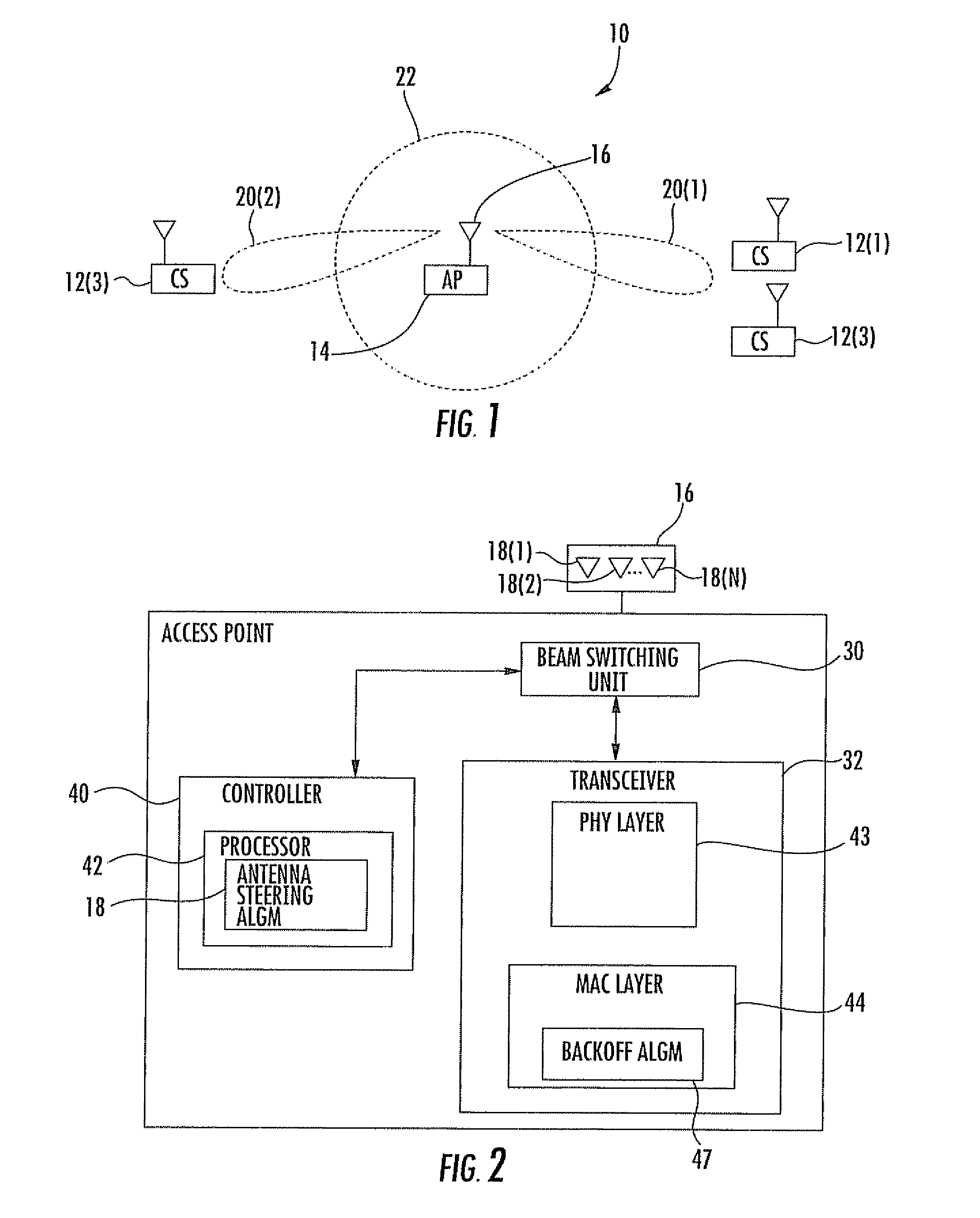
[0023] Referring initially to FIGS. 1 and 2, an 802.11 wireless local area network (WLAN) 10 includes client stations 12(1)-12(3), and an access point 14 operating with an antenna array 16 in which a directional antenna beam 20(1)-20(2) may be selected for receiving uplink transmissions for the client stations. The client stations may be generally referred to by reference 12, and the directional antenna beams may be generally referred to by reference 20....


PUM


Abstract

An access point receives uplink transmissions from client stations using directional antenna beams. The directional antenna beams are generated by an antenna array. The different directional antenna beams are assigned beam identification numbers, and a preferred antenna beam is selected for each client station. The client stations in the different antenna beam regions initiate their uplink transmissions using assigned backoff slots within the contention window. The access point selects the preferred directional antenna beam corresponding to the directional antenna beams assigned to the backoff slots.

Description

RELATED APPLICATION [0001] This application claims the benefit of U.S. Provisional Application Ser. No. 60 / 651,607 filed Feb. 10, 2005, the entire contents of which are incorporated herein by reference.FIELD OF THE INVENTION [0002] The present invention relates to the field of wireless communications, and more particularly, to an access point operating with a directional antenna in an 802.11 wireless local area network (WLAN). Background of the Invention [0003] In an 802.11 wireless local area network, an access point (AP) exchanges data with wireless users. The wireless users are also known as client stations (CS). Example client stations are personal computers operating with a wireless network card. An access point includes an antenna for sending downlink signals to the client stations. The access point is also responsible for receiving uplink signals transmitted from each client station. [0004] The most common type of antenna used to transmit and receive signals at an access poin...

Claims


Application Information

Patent Timeline
IPC IPC(8): H04L12/413H04W16/28
CPCH04B7/0695H04W16/28
Inventor LIU, KAIWANG, CARLCHANDRA, ARTYWANG, JIN
Owner INTERDIGITAL TECH CORP
Learn More