
OFDM-MIMO communication system using smart spatial symbol mapping and associated methods

a communication system and spatial symbol technology, applied in multiplex communication, orthogonal multiplex, site diversity, etc., can solve the problems of high signal-to-noise ratio, unreliable wireless link, and problems in rf circuitry design, so as to reduce the signal-to-noise ratio

Inactive Publication Date: 2006-09-21
INTERDIGITAL TECH CORP
View PDF4 Cites 21 Cited by
  • Summary
  • Abstract
  • Description
  • Claims
  • Application Information

AI Technical Summary

Benefits of technology

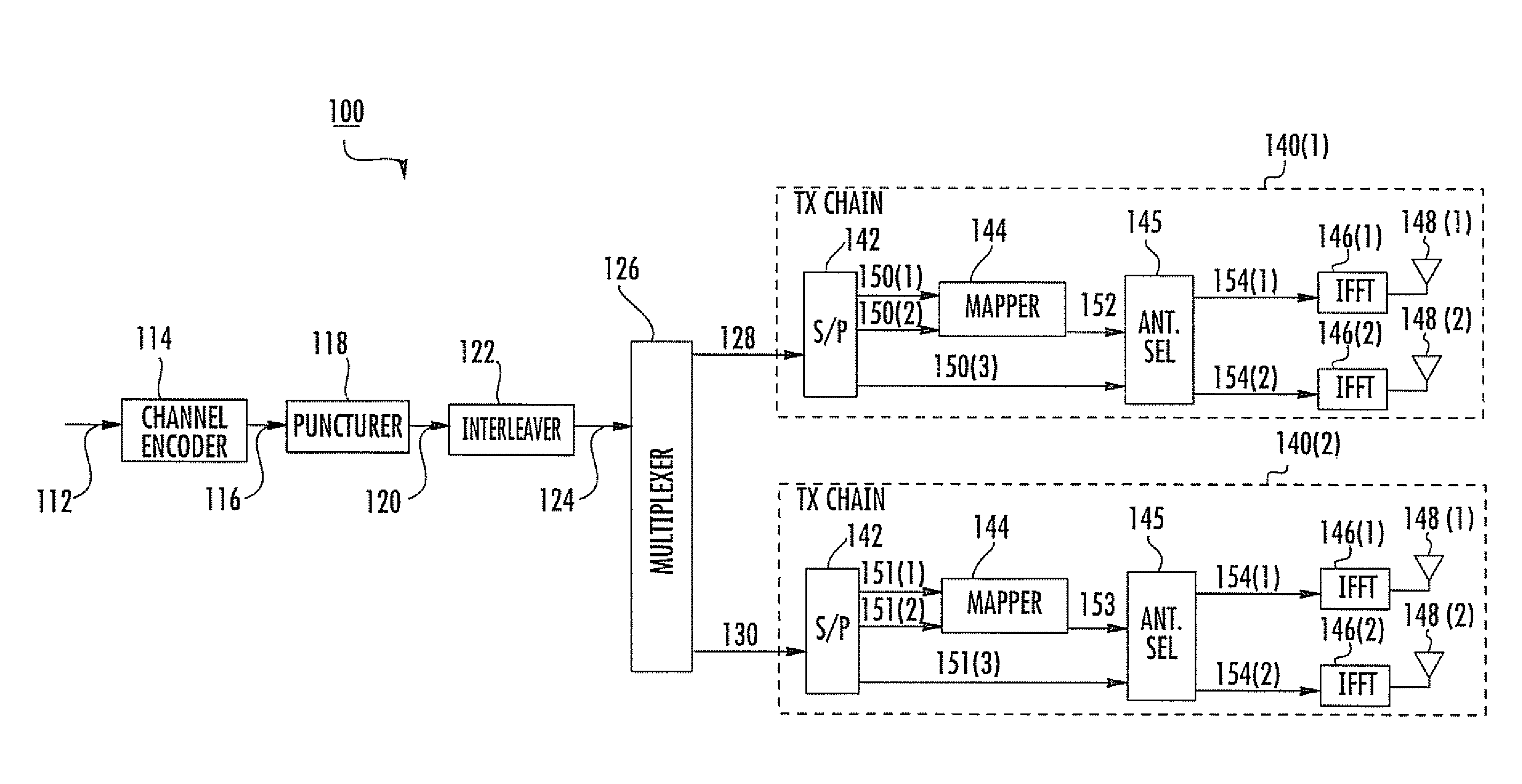
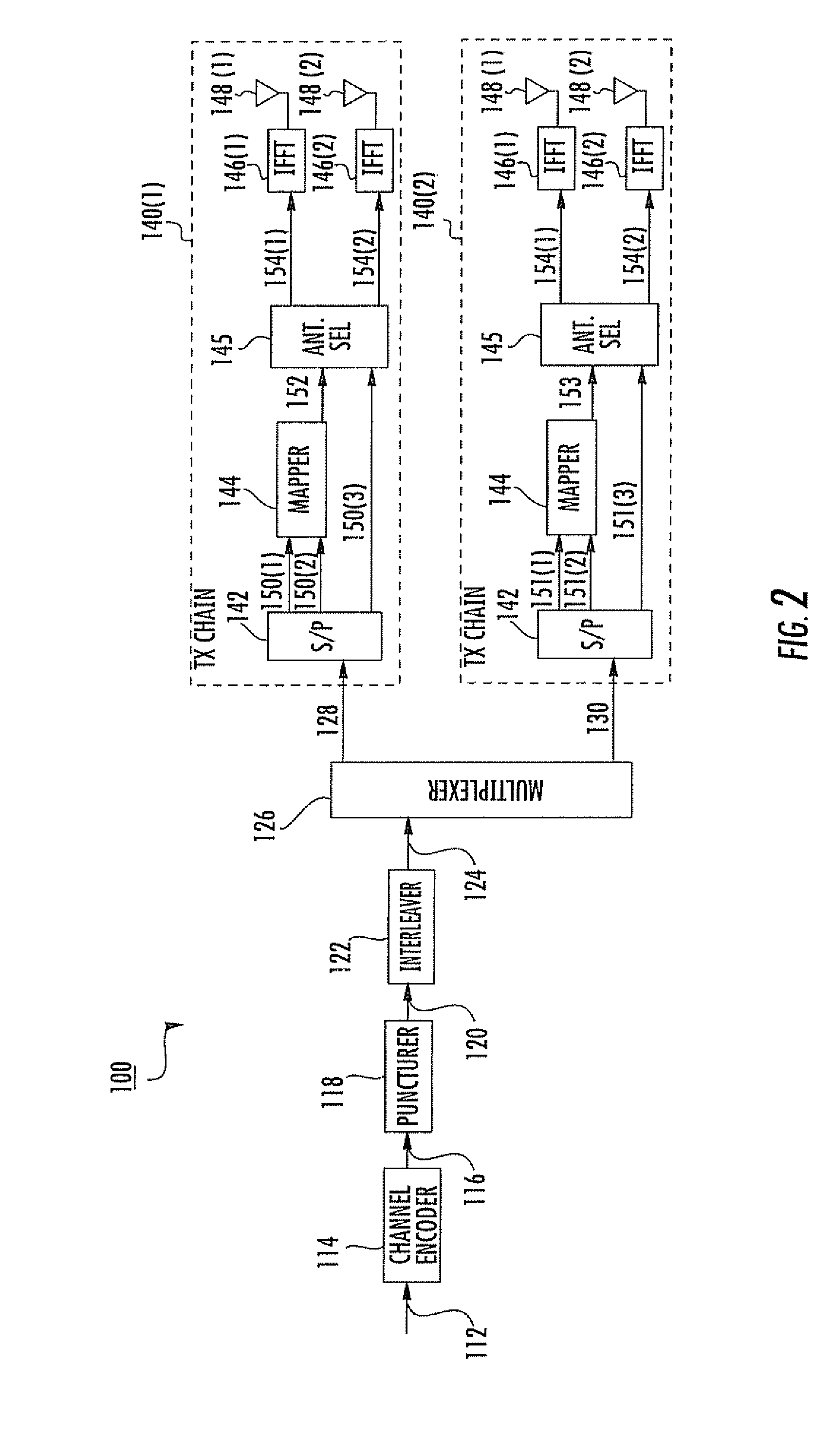
The present invention provides a robust OFDM-MIMO communication system that achieves desired bit error rates with reduced signal-to-noise ratios. The system uses a smaller signal constellation for the same data rate, requires less SNR to achieve the same packet error rate, and achieves spatial diversity by effectively distributing coded bits among multiple transmit antennas. The system also reduces peak to average ratio of the resulting OFDM waveform and improves the data link between the transmitter and receiver. The receiver uses a plurality of receive antennas, OFDM demodulators, and channel estimators to estimate RF characteristics between the transmit antennas and the receive antennas. The system also includes a method for communicating between the transmitter and receiver in the wireless communication system.

Problems solved by technology

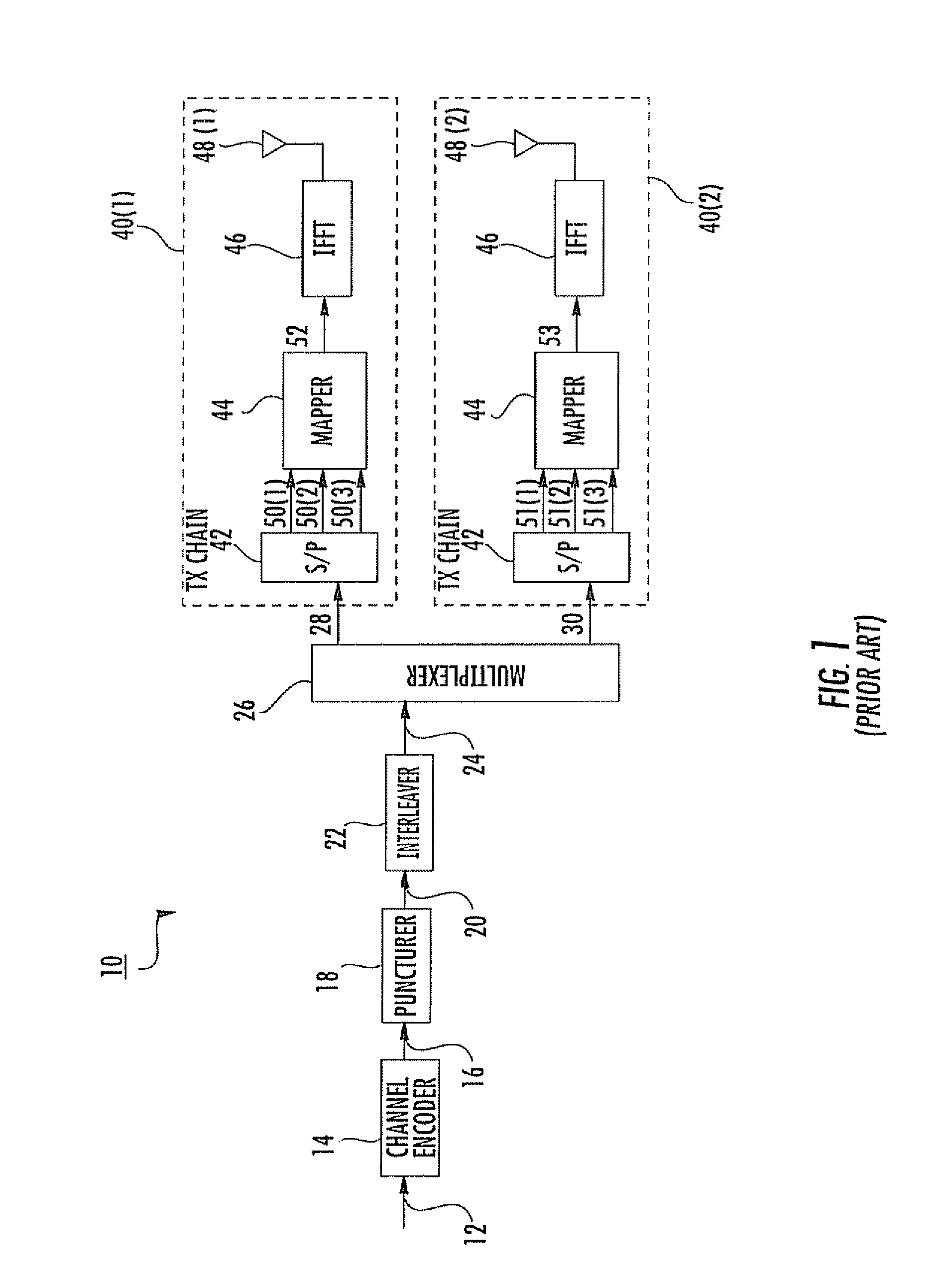
There are several potential problems associated with the conventional OFDM-MIMO transmitter 10.
However, these high-order modulation schemes require a higher signal-to-noise (SNR) ratio to achieve certain bit error rates (BER).
Modulation schemes that require high SNR to achieve certain bit error rates are adversely affected in multipath fading environments, thus causing the wireless links to be unreliable.
High PAR causes problems in RF circuitry design, especially in the power amplifiers.

Method used


Image

  • OFDM-MIMO communication system using smart spatial symbol mapping and associated methods
  • OFDM-MIMO communication system using smart spatial symbol mapping and associated methods
  • OFDM-MIMO communication system using smart spatial symbol mapping and associated methods

Examples


Embodiment Construction

[0028] The present invention will now be described more fully hereinafter with reference to the accompanying drawings, in which preferred embodiments of the invention are shown. This invention may, however, be embodied in many different forms and should not be construed as limited to the embodiments set forth herein. Rather, these embodiments are provided so that this disclosure will be thorough and complete, and will fully convey the scope of the invention to those skilled in the art. Like numbers refer to like elements throughout.

[0029] An OFDM-MIMO wireless data communication system in accordance with the present invention combines antenna pattern modulation with traditional OFDM modulation techniques. Information bits are jointly represented by channel symbols and antenna selection bits. This combination effectively uses a smaller signal constellation as compared to using only traditional modulation techniques to achieve the same data transfer rate. Moreover, this combination r...


PUM


Abstract

A transmitter in an OFDM-MIMO wireless communication system uses multiple antennas to transmit each data stream. Before the coded binary bits are mapped into channel symbols, they are divided into two groups. One group is mapped to a channel symbol as in a conventional system. Another group of binary bits is used to generate a spatial mapping index. The spatial mapping index determines which antenna is to be used to transmit the channel symbol for each subcarrier. Effectively, information bits are jointly represented by a combination of a channel symbol and an antenna that transmits the channel symbol. Therefore, to achieve the same data rate, a smaller signal constellation is required. In addition, spatial diversity can be achieved which is similar to traditional switching diversity. The number of non-zero subcarriers is reduced by half on average, which results in a lower peak to average ratio than conventional OFDM systems.

Description

RELATED APPLICATION [0001] This application claims the benefit of U.S. Provisional Application Ser. No. 60 / 655,057 filed Feb. 22, 2005, the entire contents of which are incorporated herein by reference.FIELD OF THE INVENTION [0002] The present invention relates to wireless communication systems, and more particularly, to a wireless communication system using orthogonal frequency division multiplex (OFDM) modulation and equipped with multiple transmit and receive antennas. BACKGROUND OF THE INVENTION [0003] A multiple-input multiple-output (MIMO) wireless communication system includes a plurality of antenna elements at the transmitter and a plurality of antenna elements at the receiver. A respective antenna array is formed at the transmitter and at the receiver based upon the antenna elements associated therewith. The antenna elements are used in a multi-path rich environment such that due to the presence of various scattering objects in the environment, each signal experiences multi...

Claims


Application Information

Patent Timeline
Patent Type & Authority Applications(United States)
IPC IPC(8): H04J11/00H04B7/024H04J99/00H04B7/0413
CPCH04B7/02H04L1/0618H04L5/0025H04L5/0046H04L27/2626H04L27/2647H04B7/024H04B7/0413
Inventor LI, YINGXUE
Owner INTERDIGITAL TECH CORP
Learn More