
Spread spectrum communication device and spread spectrum communication method

a technology of communication device and spread spectrum, which is applied in the field of communication device, can solve the problems of poor decoding at the reception side, complicated constitution, and increase the size of the constitution of the receiver, so as to achieve the effect of facilitating the handover between different systems

Inactive Publication Date: 2006-09-14
MITSUBISHI ELECTRIC CORP
View PDF36 Cites 16 Cited by
  • Summary
  • Abstract
  • Description
  • Claims
  • Application Information

AI Technical Summary

Benefits of technology

[0016] A spread spectrum communication device according to an aspect of the present invention is applied in a code division multiple access system for continuously transmitting frames in a normal mode, and intermittently transmitting compressed frames in a compressed mode, and is characterized in that it comprises an interleaving unit for interleaving in bit units a frame or a compressed frame, which is a unit of a transmission data stream, to minimize effects of transmission errors; a compressing / intermittent transmitting unit for compressing a frame prior to or after interleaving in the compressed mode, and moreover, intermittently outputting the compressed frame to the interleaving unit if the compressed frame has not yet been interleaved, and intermittently outputting the compressed frame to a device on a reception side if the compressed frame has been interleaved; a control unit for controlling the operation of interleaving in bit units of the interleaving unit, and the compressing / intermittent transmitting operation of the compressing / intermittent transmitting unit; the control unit controlling the interleaving unit to perform interleaving in bit units across multiple frames in the compressed mode.
[0017] According to this invention, in the compressed mode, multiple frames are interleaved in bit units to minimize effects of transmission errors, whereby it is possible to secure appropriate interleaving time in the compressed mode in the same way as in the normal mode, and consequently, poor performance caused by interleaving in bit units can be prevented.

Problems solved by technology

However, this increases the size of the constitution of the receiver, or makes the constitution complicated.
Consequently, the interleaving size is shortened which leads to a problem of poor decoding at the reception side.
Furthermore, in conventional examples such as the literature mentioned above, since the length of interleaving time is shortened when using compressed mode transmission, there is increased deterioration of signal quality with respect to fading, and, since no TPC (transmission power control) command bit is sent during non-transmission, it is not possible to achieve high-speed TPC, leaving a subsequent problem of poor signal quality.
However, since the number of spreading codes that can be used is directly proportional to the square of the code-length, there is a problem that there are extremely few spreading codes having short code-lengths, and these spreading code resources, which are vital for realizing compressed mode transmission, are consumed.

Method used


Image

  • Spread spectrum communication device and spread spectrum communication method
  • Spread spectrum communication device and spread spectrum communication method
  • Spread spectrum communication device and spread spectrum communication method

Examples


first embodiment

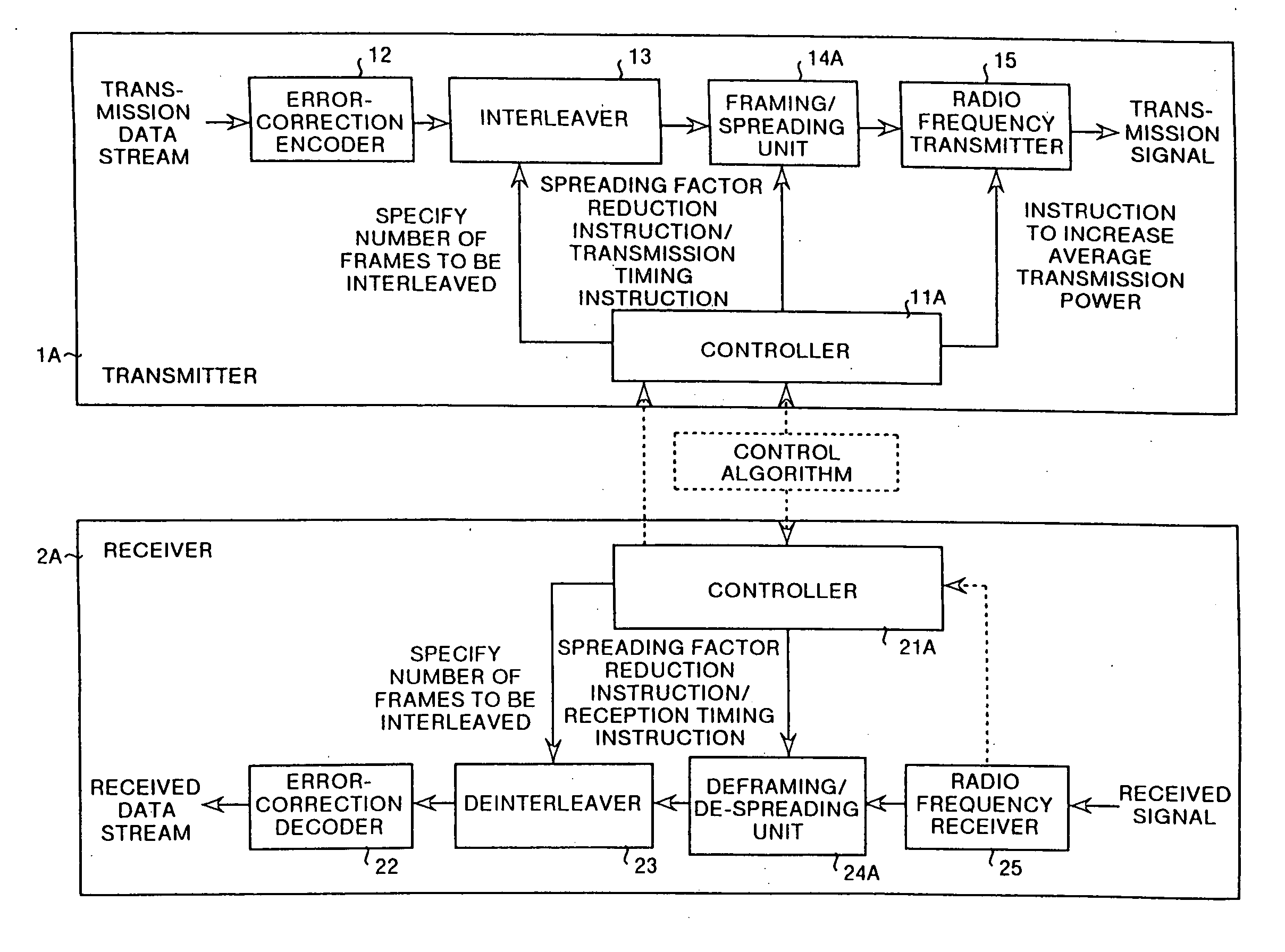
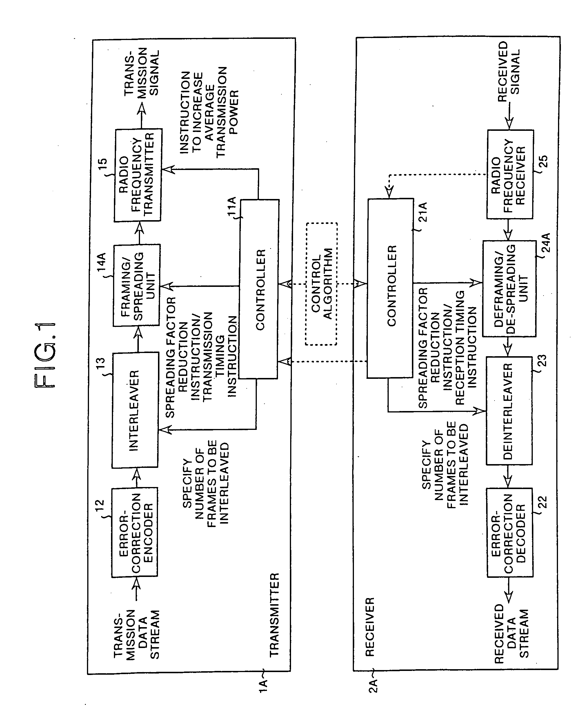
[0146] To begin with, the constitution of a CDMA system will be explained. FIG. 1 is a block diagram showing a CDMA system according to the present invention. The CDMA system comprises a transmitter 1A and a receiver 2A. Such a CDMA system is provided with both base station and mobile stations. The base station and the mobile stations carry out radio communication using a CDMA communication method.

[0147] The transmitter 1A, as shown in FIG. 1, comprises a controller 11A, an error-correction encoder 12, an interleaver 13, a framing / spreading unit 14A, a radio frequency transmitter 15, etc. Through negotiations with the receiver 2A, the controller 11A principally controls the operations of the interleaver 13, the framing / spreading unit 14A, and the radio frequency transmitter 15. Through negotiations with the receiver 2A, this controller 11A instructs, using frame numbers, objects for interleaving appropriate for a normal mode (a non-compressed mode) and compressed mode. Furthermore, ...

second embodiment

[0169] Next, frame transmission including the compressed mode will be explained. FIG. 9 is a diagram explaining frame transmission of a downlink according to the In FIG. 9, the vertical axis represents transmission rate / transmission power, and the horizontal axis represents time. In the CDMA system, during normal transmission, a period of time is provided to slot the frame and transmit it intermittently, and the strength of the other frequency carriers is measured using the fact that frames are not transmitted during that period. For this purpose, the slotted frame must be compressed, but if interleaving is performed in the same manner as in normal transmission, the interleaving time will be insufficient, and it will be impossible to obtain an adequate interleaving effect.

[0170] Accordingly, the transmission timing of the compressed frame is divided, and one part is allocated to the head of the frame, the other is allocated to the end of the same frame, securing the desired interle...

third embodiment

[0177] Firstly, frame transmission including compressed mode will be explained. FIG. 12 is a diagram explaining frame transmission of a downlink according to the In FIG. 12, the vertical axis represents transmission rate / transmission power, and the horizontal axis represents time. In the CDMA system, during normal transmission, a period of time is provided to slot the frame and transmit intermittently, and the strength of other frequency carriers is measured using the fact that frames are not transmitted during that period. For this purpose, the slotted frame must be compressed, but if interleaving is performed in the same manner as in normal transmission, there will only be half the necessary interleaving time, making it impossible to achieve adequate interleaving effects.

[0178] Accordingly, the transmission duration of the compressed frame is divided in correspondence with multiple slots, and the non-transmission period (idle period for measuring) is reduced so as not to affect t...


PUM


Abstract

In a compressed mode, a spread spectrum communication device interleaves bit units across multiple frames using an interleaver, reduces the spreading factor using a framing / spreading unit, outputs the compressed mode frames at a predetermined compressed mode frame timing, and increases the average transmission power in the compressed mode at a radio frequency transmitter. Furthermore, a handover between different frequencies is carried out by establishing synchronization to another frequency carrier, based on a first search code and a second search code which have been detected, and moreover, a handover between different communication systems is carried out by establishing synchronization to a GSM, based on an FCCH and a SCH which have been detected.

Description

TECHNICAL FIELD [0001] This invention relates to a communication device applied in a code division multiple access (CDMA) communication system and a method thereof. More particularly this invention relates to a spread spectrum communication device for improving interleave transmission and transmission power control in spread spectrum communication, and for realizing handovers between different frequencies and a method thereof. BACKGROUND ART [0002] In a CDMA cellular system, because the same carrier frequency is used repeatedly in every cell there is no need for handovers between frequencies within the same system. However, considering a case such as when existing systems are present together, there is a need for handovers between different carrier frequencies. Three points pertaining to detailed cases are described below. [0003] As a first point, in a cell where there is considerable traffic, a separate carrier frequency is used to accommodate the increased number of subscribers, a...

Claims


Application Information

Patent Timeline
Patent Type & Authority Applications(United States)
IPC IPC(8): H04B7/216H04J3/22H04J3/16H04W52/04H03M13/27H04B1/707H04B1/7073H04B1/7075H04B1/7083H04B1/7087H04B7/005H04B7/26H04J13/00H04J13/16H04L1/00H04L7/00H04W36/00H04W36/14H04W36/30H04W36/36H04W52/00H04W52/08H04W52/26H04W52/28H04W52/36H04W52/44H04W52/48H04W52/56H04W52/60H04W56/00H04W76/02
CPCG08C15/00H04B1/707H04B1/70735H04B1/7075H04B1/7083H04B1/7087H04B7/2628H04B7/2668H04B2201/70703H04J13/00H04L1/0001H04L1/0003H04L1/0009H04L1/0025H04L1/0026H04L1/004H04L1/0042H04L1/0047H04L1/0056H04L1/0071H04L1/0083H04W36/0088H04W36/30H04W52/08H04W52/267H04W52/28H04W52/287H04W52/288H04W52/36H04W52/362H04W52/367H04W52/44H04W52/48H04W52/56H04W52/60H04W56/00Y02B60/50H04W28/06H04J13/10
Inventor YANO, YASUHIROMURAI, HIDESHI
Owner MITSUBISHI ELECTRIC CORP
Learn More