
Method and system for reducing end station latency in response to network congestion

a network congestion and end station technology, applied in the field of communication networks, can solve the problems of routers and switches dropping frames, switches and routers have limited resources to store, congestion may occur, etc., and achieve the effect of reducing end station latency

Inactive Publication Date: 2006-09-14
AVAGO TECH WIRELESS IP SINGAPORE PTE
View PDF16 Cites 69 Cited by
  • Summary
  • Abstract
  • Description
  • Claims
  • Application Information

AI Technical Summary

Benefits of technology

[0009] A system and/or method is provided for reducing end station latency in response to network congestion, substanti...

Problems solved by technology

These switches and routers have limited resources to store frames that are being switched or routed from their source to their destination(s).
During routing, congestion may happen as a result of a temporary shortage of buffers in a switch or a router.
As a result of this congestion, these routers and switches may drop frames due to the temporary shortage of buffers.
For example, over subscription or over-use of an output port may result in dropped frames due to congestion.
A switch or router will buffer excess data but eventually will run out of buffers if the offered load is much greater than an amount of data that the switch has the capability to drain or to buffer.
Higher data speeds, for example 10 Gbits / sec, may impose yet higher requirements for a shorter control loop or for deeper buffers that are expensive and in some cases financially impractical.
Coupled with some latencies in the EPs, it may be sufficiently high to render this early indication prior to dropping packets suboptimal or in certain instances unworkable.

Method used


Image

  • Method and system for reducing end station latency in response to network congestion
  • Method and system for reducing end station latency in response to network congestion
  • Method and system for reducing end station latency in response to network congestion

Examples


Embodiment Construction

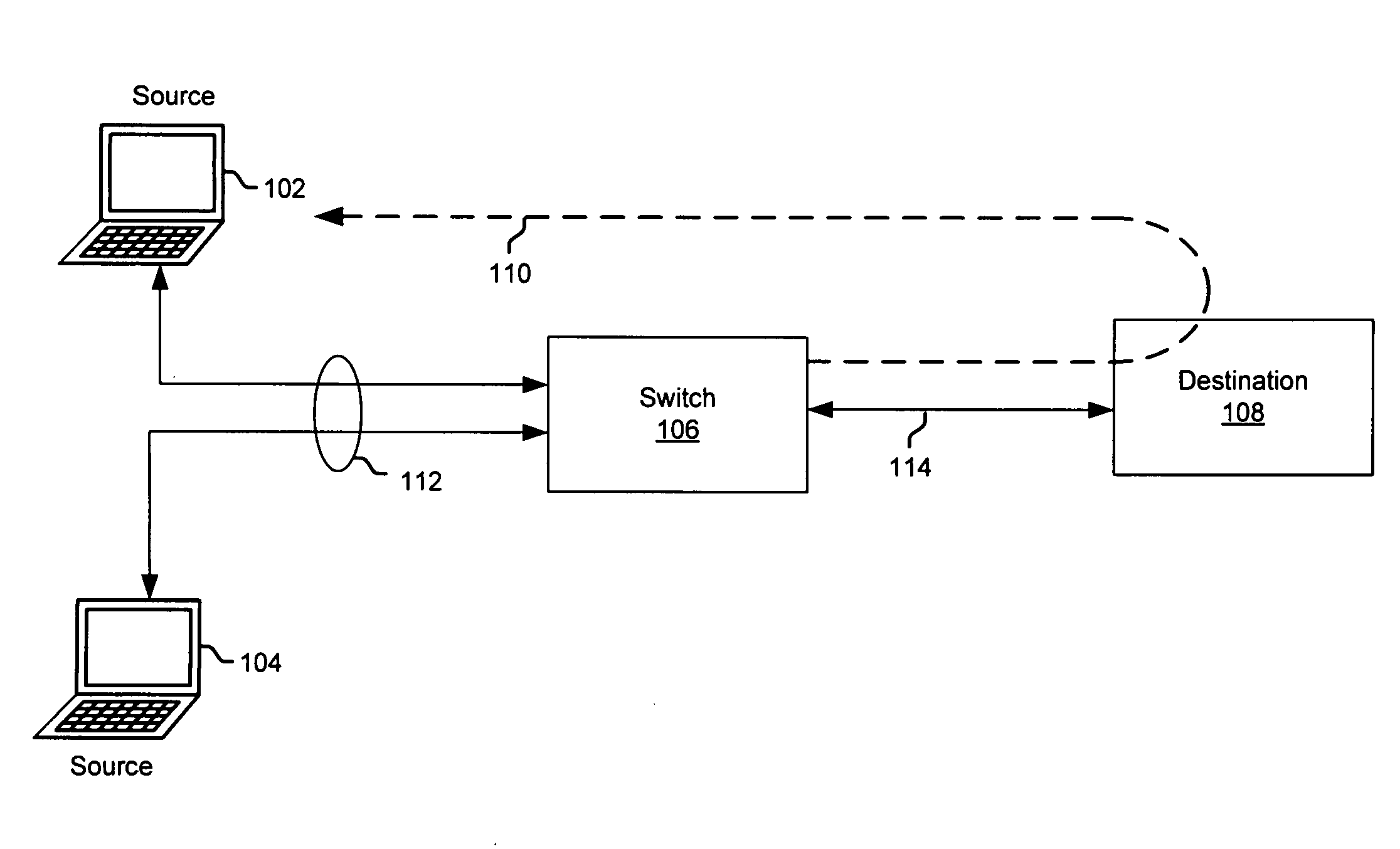
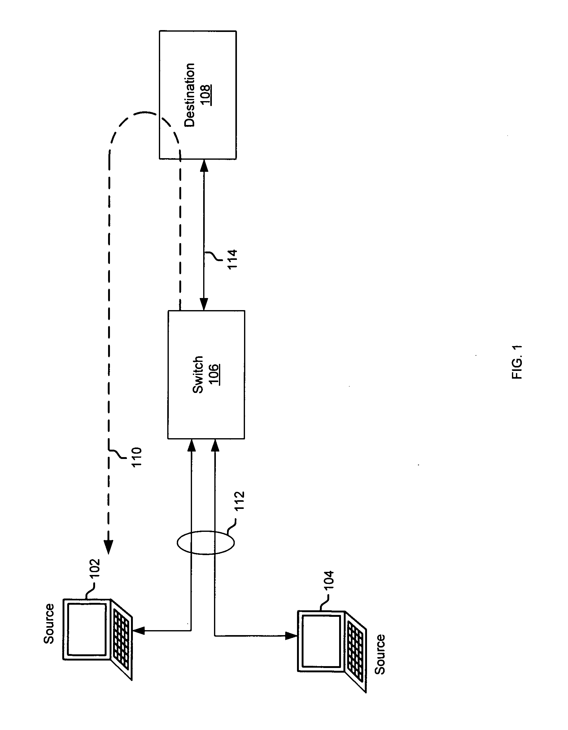
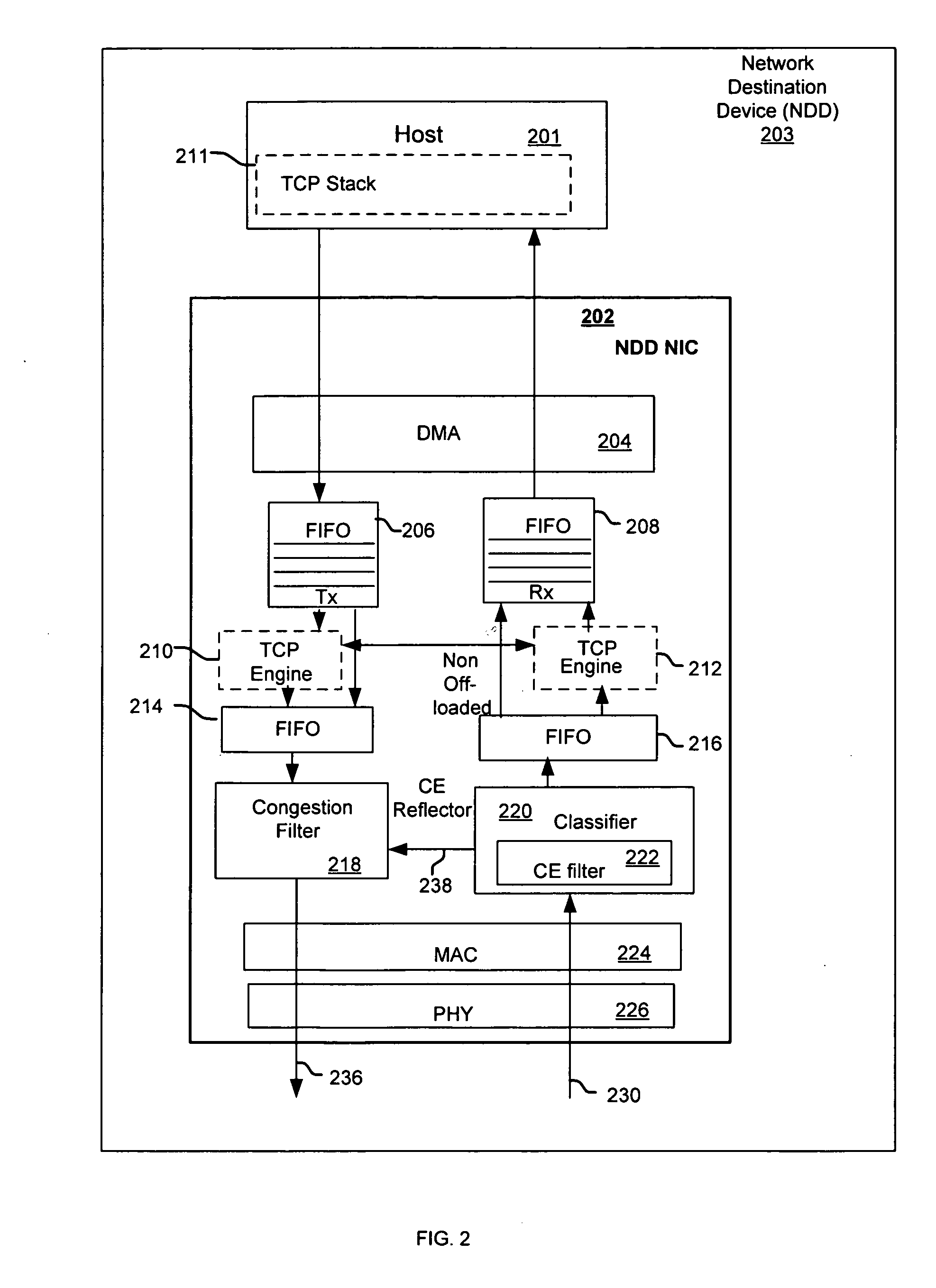
[0019] Certain embodiments of the invention may be found in a method and system for reducing end station latency in response to network congestion. Congestion indication indicating network traffic congestion may be communicated from a switching device to a network source device and / or to a network destination device. In response to the received congestion indication, a network destination device may set congestion indication flags, such as explicit congestion notification (ECN)-Echo flags, in network frames being sent to the network source device on the same flow, such as TCP ACK frames, in instances when L3 / L4 signaling is used. The network frames with set congestion indication flags may be communicated to a network source device. Latency may then be reduced within the network source device by taking an immediate action of reducing the rate or rate limiting the transmission of to-be transmitted network frames that are part of the TCP flow or Class of Service signaled in hardware, b...


PUM


Abstract

Methods and systems for processing network data are disclosed herein and may include receiving from a switching device, a congestion indicator that indicates congestion. In response to the congestion indicator, latency of reaction by a source end point, may be reduced by preventing introduction of queued up new frames to affected flow or CoS before the local stack adjusts its rate to congestion conditions and / or by rate limiting the processing of unprocessed network frames in hardware. The unprocessed network frames may include unprocessed network frames of a particular type. In response to the received congestion indicator, by a destination end point, congestion indicator flags may be set in processed network frames of the particular type, faster than an expected reaction of a local stack. The congestion indicator flags may be explicit congestion notification (ECN)-Echo flags.

Description

CROSS-REFERENCE TO RELATED APPLICATIONS / INCORPORATION BY REFERENCE [0001] This application makes reference to, claims priority to, and claims the benefit of: [0002] U.S. Provisional Application Serial No. 60 / 662,068, filed Mar. 14, 2005; and [0003] U.S. Provisional Application Serial No. 60 / 750,245, filed Dec. 14, 2005. [0004] The above stated applications are hereby incorporated herein by reference in their entirety.FIELD OF THE INVENTION [0005] Certain embodiments of the invention relate to communication networks. More specifically, certain embodiments of the invention relate to a method and system for reducing end station latency in response to network congestion. BACKGROUND OF THE INVENTION [0006] A network may comprise a plurality of end points (EPs) and a plurality of switches and / or routers. These switches and routers have limited resources to store frames that are being switched or routed from their source to their destination(s). During routing, congestion may happen as a r...

Claims


Application Information

Patent Timeline
IPC IPC(8): H04J1/16H04L12/56
CPCH04L47/10H04L47/11H04L47/2441H04L47/263H04L47/32Y02B60/31Y02D30/50
Inventor ZUR, URI EL
Owner AVAGO TECH WIRELESS IP SINGAPORE PTE
Learn More