Illuminating unit and projection type image display apparatus using the same
a technology of projection type and display apparatus, applied in fixed installation, lighting and heating apparatus, instruments, etc., can solve the problem of not having a suggestion to satisfy this requirement, and achieve the effect of discharging the heat generated by the light emitting devi
- Summary
- Abstract
- Description
- Claims
- Application Information
AI Technical Summary
Benefits of technology
Problems solved by technology
Method used
Image
Examples
first embodiment
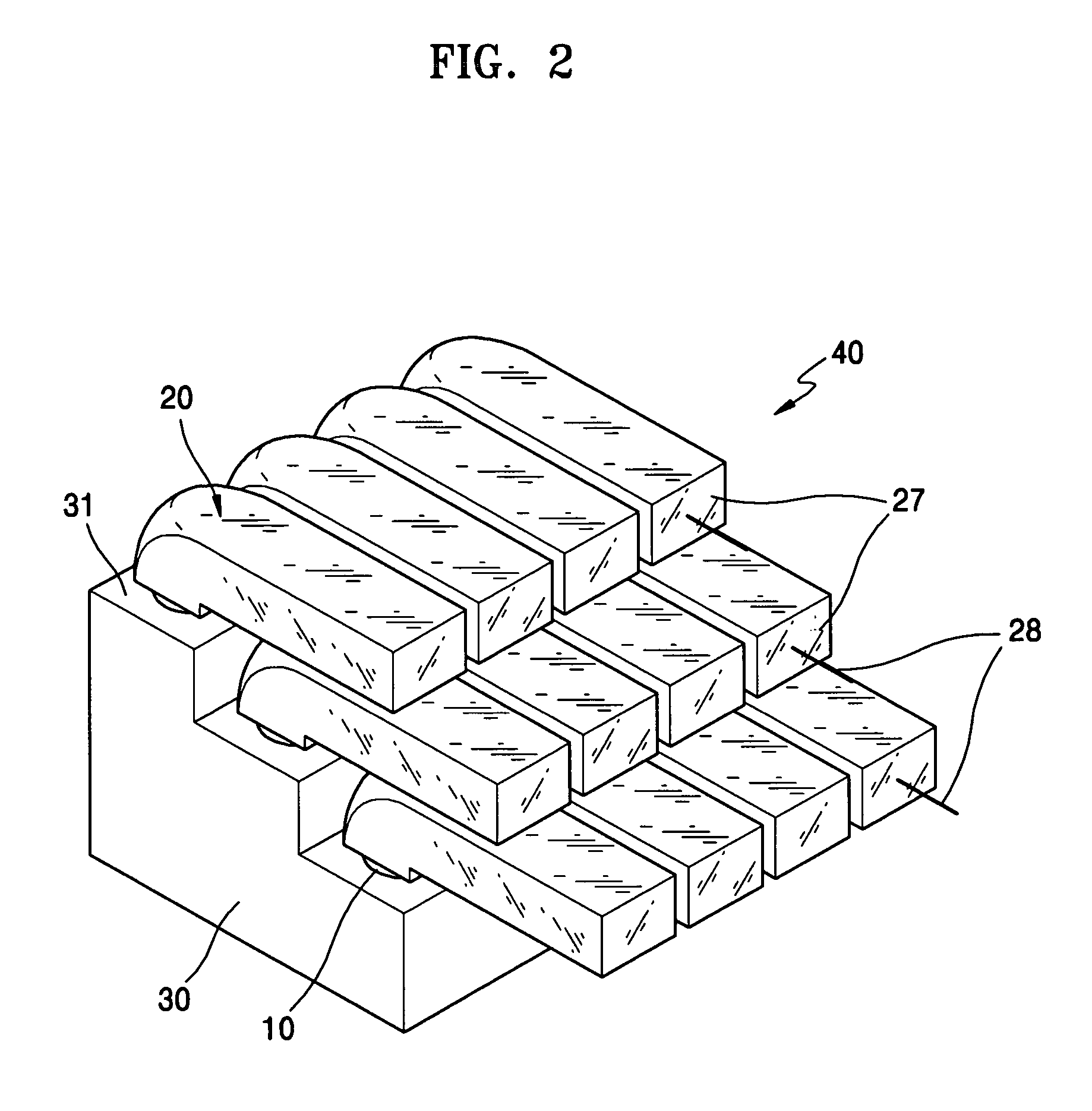
[0034]FIG. 2 is a perspective view of an example of an illuminating unit according to the present invention.
[0035] The illuminating unit 40 has a fixing member 30, a plurality of light emitting diodes (LEDs) 10, and collimators 20 coupled to the LEDs 10.
[0036] The fixing member 30 has a 3-step structure. The top surface 31 of each step is sufficiently large to mount the collimator 20. The LEDs 10 are installed on each top surface 31, and the collimator 20 covers the LED 10, so that the light beam output from the LED is collimated by the collimator 20. Further, a plurality of collimators 20 are arranged to guide the light beams to the same direction. That is, the collimators 20 are arranged in such a way that the normal vectors of the light output surfaces 27 of the collimators 20 are directed to the same direction.
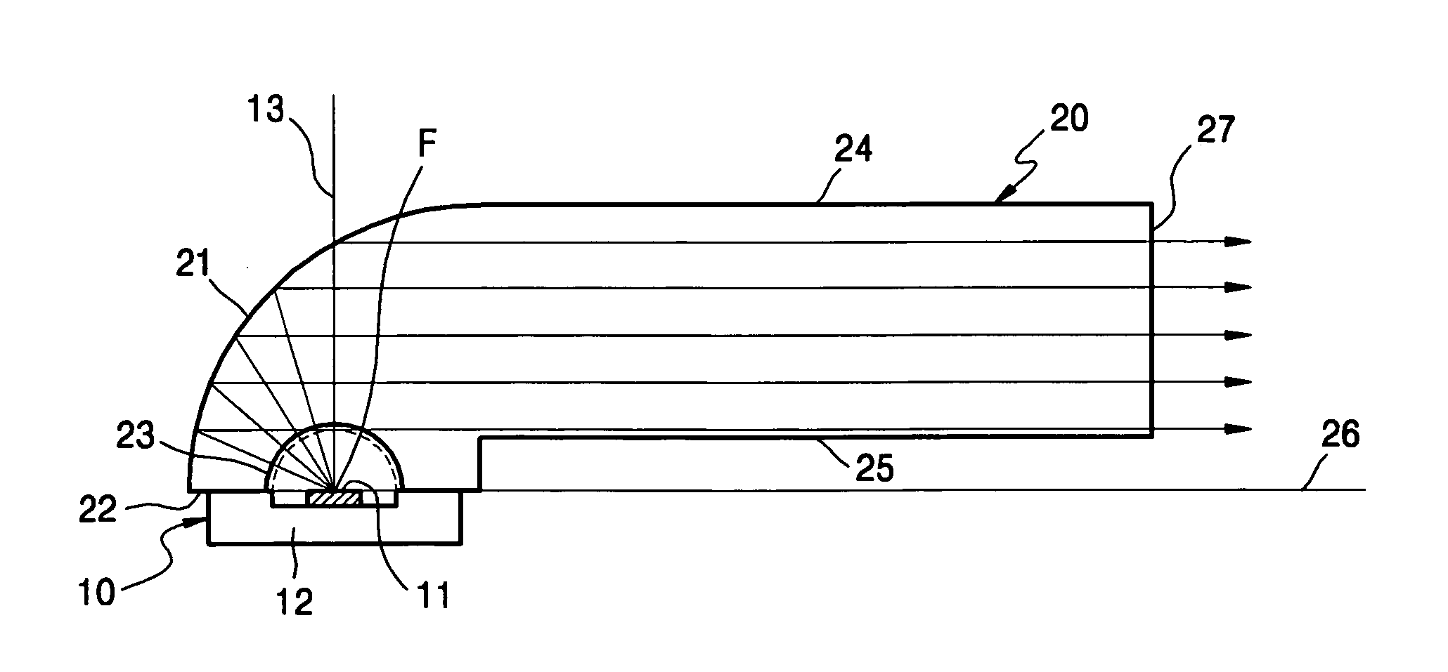
[0037] The LEDs 10 and the collimators 20 will now be described in more detail with reference to FIGS. 3 and 4.
[0038] The LED 10 has an LED chip 11 mounted on a substra...
second embodiment
[0046]FIG. 5 is a perspective view of an illuminating unit according to the present invention, and FIG. 6 is a cross-sectional view along a line VI-VI of FIG. 5.
[0047] In the second embodiment, the fixing member 30 and the LEDs 10 have the same structure as in the first embodiment. Also, first through third collimators 35a, 35b, and 35c according to the second embodiment have the same structure as in the first embodiment, except that the lengths of the light guide sections 36a, 36b, and 36c are different.
[0048] Referring to FIGS. 5 and 6, the illuminating unit 50 includes a fixing member having a 3 step structure, a plurality of LEDs mounted on the top surfaces of each step, and first through third collimators 35a, 35b, and 35c.
[0049] The LEDs 10 are mounted on the top surfaces 31 of the steps. The first through third collimators 35a, 35b, and 35c are installed to cover the LEDs 10 so that the light beams from LEDs 10 can be collected. Also, the first through third collimators 35a...
third embodiment
[0057]FIG. 9 is a perspective view of an illuminating unit 80 having first and second fixing members 70a and 70b according to the present invention.
[0058] The illuminating unit 80 according to the third embodiment of the present invention includes LEDs 10, upper and lower collimators 75a and 75b, and first and second fixing members 70a and 70b having a 2-step structure. The first stepped top surface 71a of the first fixing member 70a faces the second stepped top surface 71b of the second fixing member 70b.
[0059] The LEDs 10 used in this embodiment have the same configuration as those used in the first embodiment, and the upper and lower collimators 75a and 75b also have the same configuration as those used in the first embodiment, except for the lengths of the light guide sections. In comparison with the first and second embodiments, the first and second fixing members 70a and 70b according to the third embodiment have a 2-step structure.
[0060] The light guide sections of the uppe...
PUM
| Property | Measurement | Unit |
|---|---|---|
| refractive index | aaaaa | aaaaa |
| wavelengths | aaaaa | aaaaa |
| length | aaaaa | aaaaa |
Abstract
Description
Claims
Application Information
 - R&D
- Intellectual Property
- Life Sciences
- Materials
- Tech Scout
- Unparalleled Data Quality
- Higher Quality Content
- 60% Fewer Hallucinations
Browse by: Latest US Patents, China's latest patents, Technical Efficacy Thesaurus, Application Domain, Technology Topic, Popular Technical Reports.
© 2025 PatSnap. All rights reserved.Legal|Privacy policy|Modern Slavery Act Transparency Statement|Sitemap|About US| Contact US: help@patsnap.com


