
Hub dynamo

a hub dynamo and hub technology, applied in the direction of optical signal, magnetic circuit shape/form/construction, cycle equipment, etc., can solve the problems of reduced size and weight, prone to magnetic saturation, and large loss of electric power generation on each power-generating unit, so as to reduce the size and weight of the hub dynamo, efficiently collect, and supply stably

Inactive Publication Date: 2006-09-14
MITSUBA CORP
View PDF3 Cites 7 Cited by
  • Summary
  • Abstract
  • Description
  • Claims
  • Application Information

AI Technical Summary

Benefits of technology

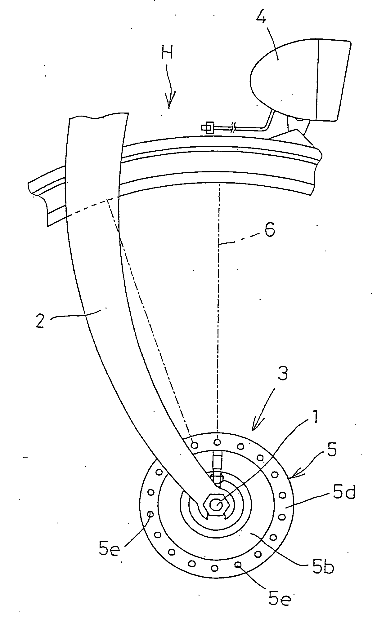
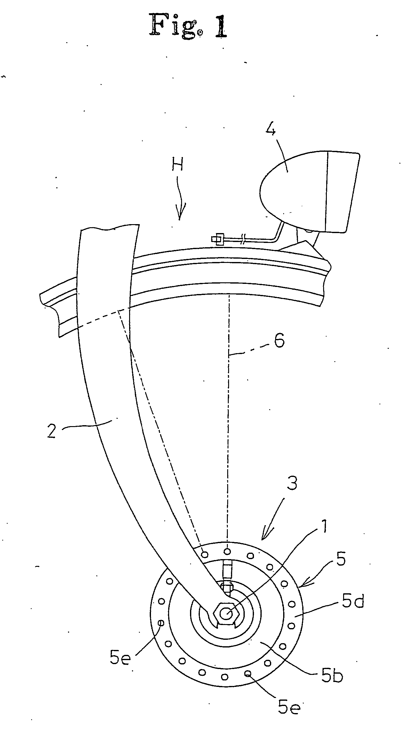
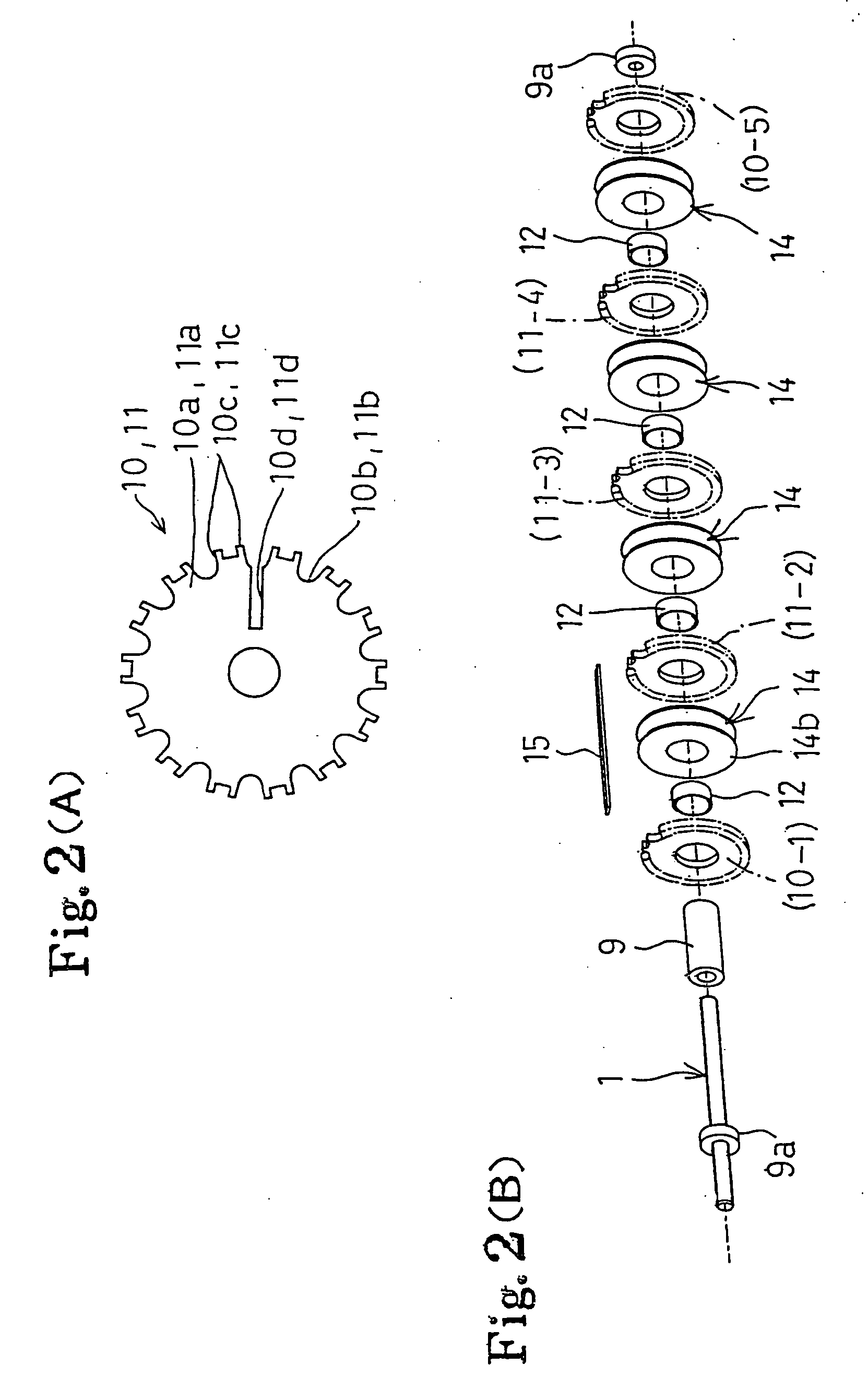
The patent text describes a hub dynamo for a bicycle that has a smaller size and higher efficiency in power generation compared to previous designs. The arrangement of the magnetic flux collectors and the main / sub iron cores reduces the size of the hub and increases the magnetic path, resulting in a higher voltage generation of electric power. The use of a simple structure and the arrangement of the magnetic flux collectors and the iron cores also reduces the loss of electric power. The hub dynamo is well-balanced and generates a high amount of magnetic flux, resulting in a superior electric power generation. The arrangement of the magnetic flux collectors and the iron cores also reduces magnetic saturation and simplifies the structure. The use of a pull-out groove for pulling out the coil wire to the outside further simplifies the structure.

Problems solved by technology

Therefore, there arises a problem that the above conflicts with requests for a reduction in size and weight.
And further, high precision is required for the assembly thereof Furthermore, when a difference is generated in the distance (gap) between the permanent magnets and pole pieces facing each other, the balance of the electric power generation on each power-generating unit is largely lost.
Therefore, there resides a problem that magnetic saturation is apt to easily occur at the supporting portion, and the supporting strength is insufficient.
These are the disadvantages that the disclosure intends to solve.
Thus, efficiency in power generation of the hub dynamo is not reduced.

Method used


Image

  • Hub dynamo
  • Hub dynamo
  • Hub dynamo

Examples


first embodiment

[0069] Further, unlike the above first embodiment, the sub iron cores 11 are not formed of one plate member, but may be formed by laminating a plurality of thin plate members. In this case, compared to the iron core 11 having a single plate member, eddy current loss can be reduced. As a result, the efficiency in power generation can be prevented from being reduced. Additionally, when fixing the magnetic flux collectors to the sub iron cores 11 by a manner of caulking, the fixing force at the fixing portions can be made uniform Thus, a highly reliable hub dynamo 3 can be obtained. Further, the main iron cores 10 can also be formed by laminating a plurality of thin plate members, the same as the sub iron cores 11. In this case also, the same effects can be obtained.

third embodiment

[0070] Also, an arrangement according to a third exemplary embodiment as shown in FIGS. 7 to 9 is possible. In a hub dynamo 17 according to this third embodiment, the basic structure is the same as that of the above-described embodiments. That is, 14-pair of permanent magnets 18a are provided to the inner circumference of the yoke 18. Between the main iron cores 19 facing each other, two sub iron cores 20 are provided to form first to third coil chambers CR-1, CR-2, CR-3. In this embodiment, the main / sub iron cores 19, 20 are constructed of a plurality of laminated plate members 19a, 20a to increase the efficiency in power generation. Further, in this embodiment, the same as in the case of the above-described circumference of the respective iron cores 19, 20, are connected to the adjacent iron cores 19, 20 so as to be magnetized to a polarity different from each other. Here, the magnetic flux collectors 21 are provided with inclined (tapered) portions 21a and narrower portions 21b. ...


PUM


Abstract

A hub dynamo is compacted into a small diameter size while ensuring the generation of a high voltage of electric power. A coil chamber formed between a pair of main iron 10 cores, is partitioned in the axial direction by at least one sub iron 11 core to form a plurality of coil chambers. On the coil chambers a coil wire is wound such that the winding direction changes alternately between adjacent coil chambers. Magnetic flux collectors are connected to the outer circumference of the main / sub iron cores and include a plurality of first magnetic flux 15 collectors connected with the odd numbered iron cores and a (counting from either end) and a plurality of second magnetic flux collectors connected with the even numbered iron cores cores.

Description

[0001] This application is the U.S. National Stage of PCT / JP2004 / 010743, filed Jul. 21, 2004, which claims priority from JP2003-280057, filed Jul. 25, 2003, the entire disclosures of which are incorporated herein by reference thereto.BACKGROUND OF THE INVENTION [0002] The disclosure pertains to a hub dynamo mounted on forks constituting a part of a frame of a bicycle. [0003] Generally, some bicycles are provided with a dynamo on an axle attached to the forks constituting a part of the frame. With rotation of a wheel which accompanies traveling of the bicycle, electric power is generated and a headlamp lights up using the electric power generated thereby. [0004] A hub dynamo, as an electric power generator, is required to provide a compact size and to ensure a high voltage without increasing the speed. For example, a dynamo as described below has been proposed. That is, at the inner circumference of the rotor (yoke) at the wheel side, permanent magnets are provided in a state that th...

Claims


Application Information

Patent Timeline
Patent Type & Authority Applications(United States)
IPC IPC(8): H02K7/18H02K1/14H02K21/22
CPCH02K1/145H02K7/1846H02K21/227
Inventor ITOI, KENJIMINAMI, HIDEYUKIYODA, TAKESHITAKAKUSAGI, RYUICHI
Owner MITSUBA CORP
Learn More