
Compact hydropower generator adopting multiple rotary drums

Inactive Publication Date: 2006-09-14
PARK JAE HONG
View PDF7 Cites 7 Cited by
  • Summary
  • Abstract
  • Description
  • Claims
  • Application Information

AI Technical Summary

Benefits of technology

[0011] Therefore, the present invention has been made in view of the above problems, and it is a first object of the present invention to provide a compact hydropower generation apparatus using multiple rotary drums, which enables small-scale power generation through the use of a small river.
[0012] It is a second object of the present invention to provide a small-scale nonpolluting hydroelectric power generation apparatus that can be installed near a small river wherever there is a gentle gradient while having a minimum effect on the ecosystem of the small river.
[0013] It is a third object of the present invention to provide a compact hydropower generation apparatus that can achieve an efficient utilization of installation space while achieving minimum environmental disruption.
[0014] It is a fourth object of the present invention to provide a compact hydropower generation apparatus that can achieve a considerable reduction in use of fossil fuel and energy.
[0015] It is a fifth object of the present invention to provide a compact hydropower generation system that can transmit sufficient power to a generator even when the peripheral area around a small river has no gradient, and can achieve great power in spite of a relatively small overall size thereof.
[0016] It is a sixth object of the present invention to provide a compact hydropower generation system using a plurality of rotary drums that can achieve an improvement in product quality and reliability.

Problems solved by technology

However, the above mentioned capacity is only about 3.0% of the potential amount.
However, the conventional small-sized hydropower generation apparatus has a severe problem in that it cannot secure an essential water intake source around the small river, and suffers from a structural limit in that it cannot transmit a large amount of power to the generator.
For these reasons, the conventional small hydropower generation apparatus tends to fail to generate sufficient power.

Method used


Image

  • Compact hydropower generator adopting multiple rotary drums
  • Compact hydropower generator adopting multiple rotary drums
  • Compact hydropower generator adopting multiple rotary drums

Examples


Embodiment Construction

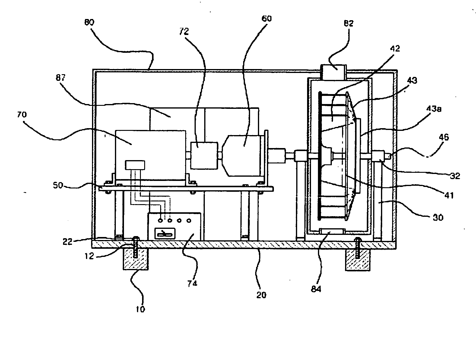
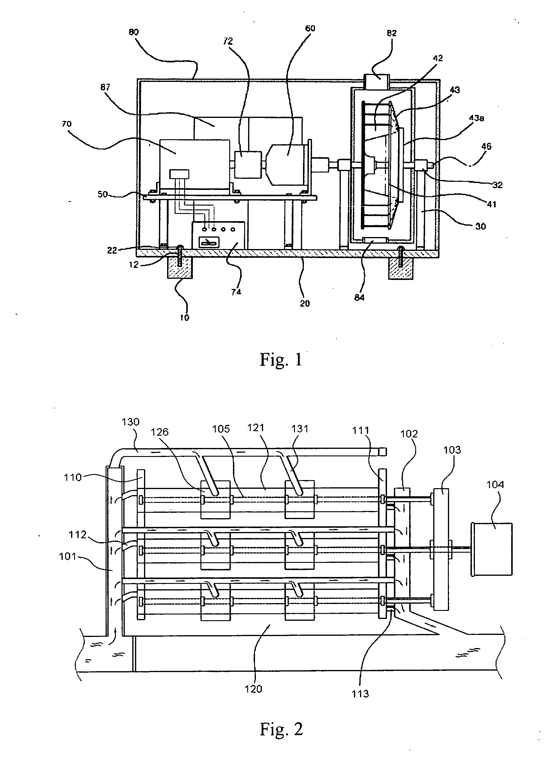
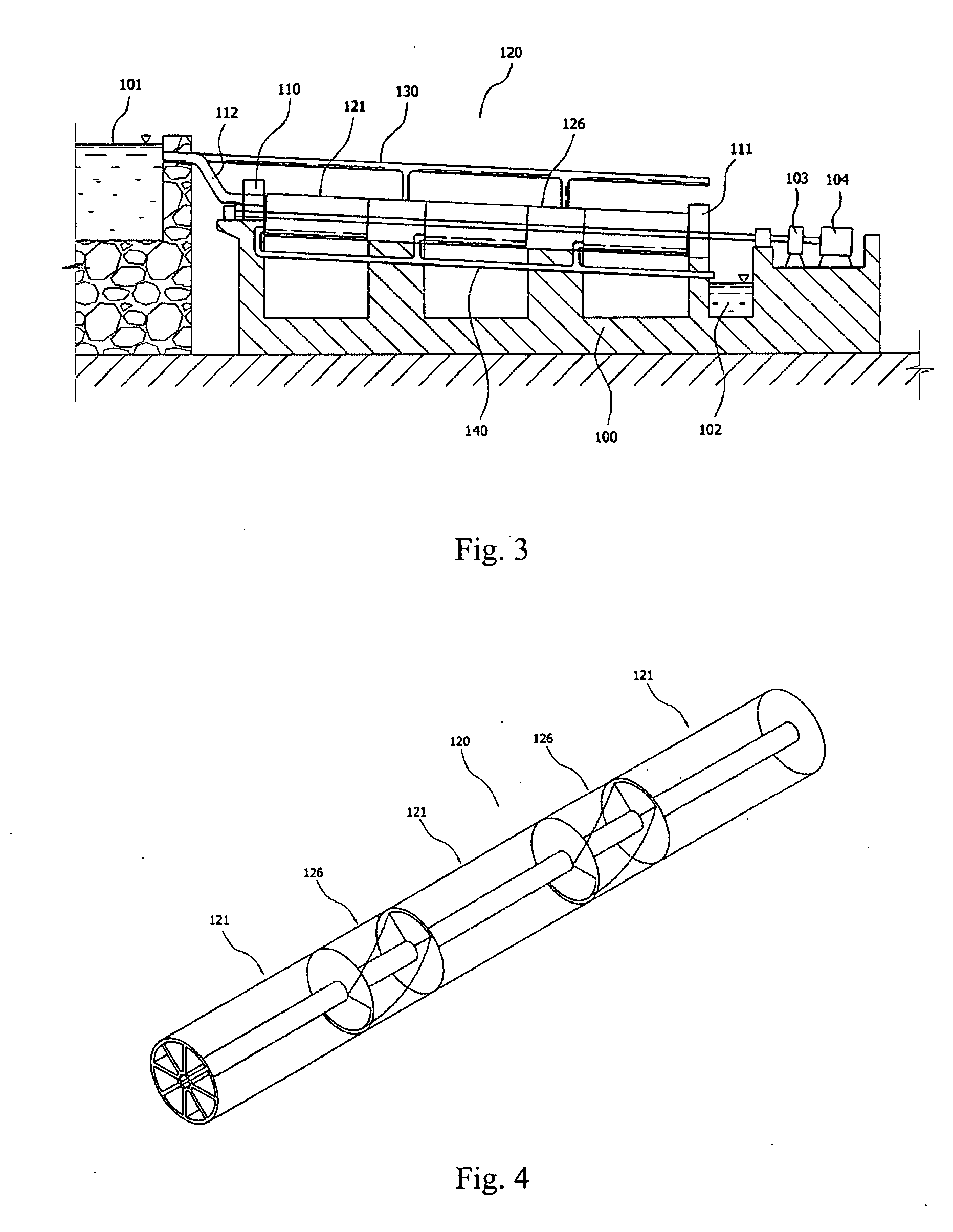
[0030] Now, preferred embodiments of a compact hydropower generating apparatus using multiple rotary drums in accordance with the present invention will be explained with reference to FIGS. 2 through 12.

[0031] In the following description of the present invention, a detailed description of known functions and configurations incorporated herein will be omitted when it may make the subject matter of the present invention rather unclear.

[0032] Also, the terms used in the following description are terms defined taking into consideration the functions obtained in accordance with the present invention. The definitions of these terms should be determined based on the whole content of this specification because they may be changed in accordance with the preference of a manufacturer or a usual practice.

[0033] The compact hydropower generation apparatus using a plurality of rotary drums in accordance with the present invention is an apparatus designed to enable small-scale power generation...


PUM


Abstract

A compact hydropower generator adopting multiple rotary drums comprises a water reservoir for changing the flow direction of water that flows along a river and for temporarily storing the water. A base body is located at a lower side of the water reservoir and has a drainage way formed at an end of a downwardly inclined portion thereof. An upper closing member and a lower closing member are provided at opposite sides of an upper end of the base body. The upper closing member is configured to communicate with the water reservoir, and the lower closing member is configured to communicate with the drainage way through a plurality of drain pipes. A power generating unit is located between the upper and lower closing member. When the water stored in the water reservoir is introduced thereinto through a plurality of water supply pipes, the power generating device rotates about a plurality of shafts due to the potential energy of the water to obtain power. An accelerator and a generator are coupled to the lower ends of the shafts.

Description

BACKGROUND OF THE INVENTION [0001] 1. Field of the Invention [0002] The present invention relates to a compact hydropower generating apparatus adopting multiple rotary drums, and more particularly, to a compact hydropower generation system having the following advantages: small-sized power generation utilizing a small river; easy installation of a small-scale nonpolluting hydroelectric power plant around the small river wherever there is a gentle gradient while achieving a minimum effect on the ecosystem of the small river; an efficient utilization of installation space with minimum environmental disruption; a considerable reduction in use of fossil fuel and energy; and an improvement in product quality and reliability. [0003] 2. Description of the Related Art [0004] For countries suffering from a serious shortage of energy sources and showing a high degree of dependence upon imported energy, it is important to achieve maximum use of existing domestic energy sources for the stabiliz...

Claims


Application Information

Patent Timeline
IPC IPC(8): F03B13/00F03B13/10H02P9/04
CPCF01D1/38F03B5/00Y02E10/20
Inventor PARK, JAE-HONG
Owner PARK JAE HONG
Learn More