
Steering shaft boot

a technology for steering shafts and boots, which is applied in the direction of mechanical equipment, couplings, transportation and packaging, etc., can solve the problems of time-consuming, time-consuming, and troublesome assembling and setting work of the right position, and achieve the effect of reducing the possibility of air permeable clearance, time-consuming, and increasing the cost of the steering shaft boo

Inactive Publication Date: 2006-09-07
KINUGAWA RUBBER IND CO LTD
View PDF4 Cites 22 Cited by
  • Summary
  • Abstract
  • Description
  • Claims
  • Application Information

AI Technical Summary

Benefits of technology

The present invention provides a steering shaft boot that is made of molded resin and integrally connected inner and outer boot portions, which eliminates the need for separate parts and reduces the cost of assembly. Additionally, the invention provides an arrangement where the steering shaft boot is secured to a panel member while covering the steering shaft. This arrangement includes a bracket that tightly receives mutually contacting parts of the panel member and the steering shaft boot. The technical effects of the invention include improved sealing of the steering shaft bore, reduced assembly and setting work, and reduced air permeable clearance between the inner and outer rubber boots.

Problems solved by technology

However, in the above-mentioned steering shaft boot, the inner and outer rubber boots that constitute the double layer boot unit are separate parts, and thus, assembling the steering shaft boot and setting the same to a right position need a troublesome and time-consumed assembling and setting work.
Furthermore, due to separate production of the inner and outer rubber boots, cost of the steering shaft boot is inevitably increased.

Method used


Image

  • Steering shaft boot
  • Steering shaft boot
  • Steering shaft boot

Examples


first embodiment

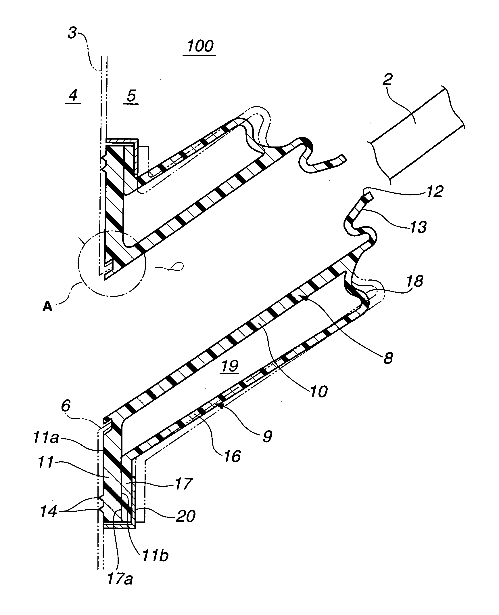
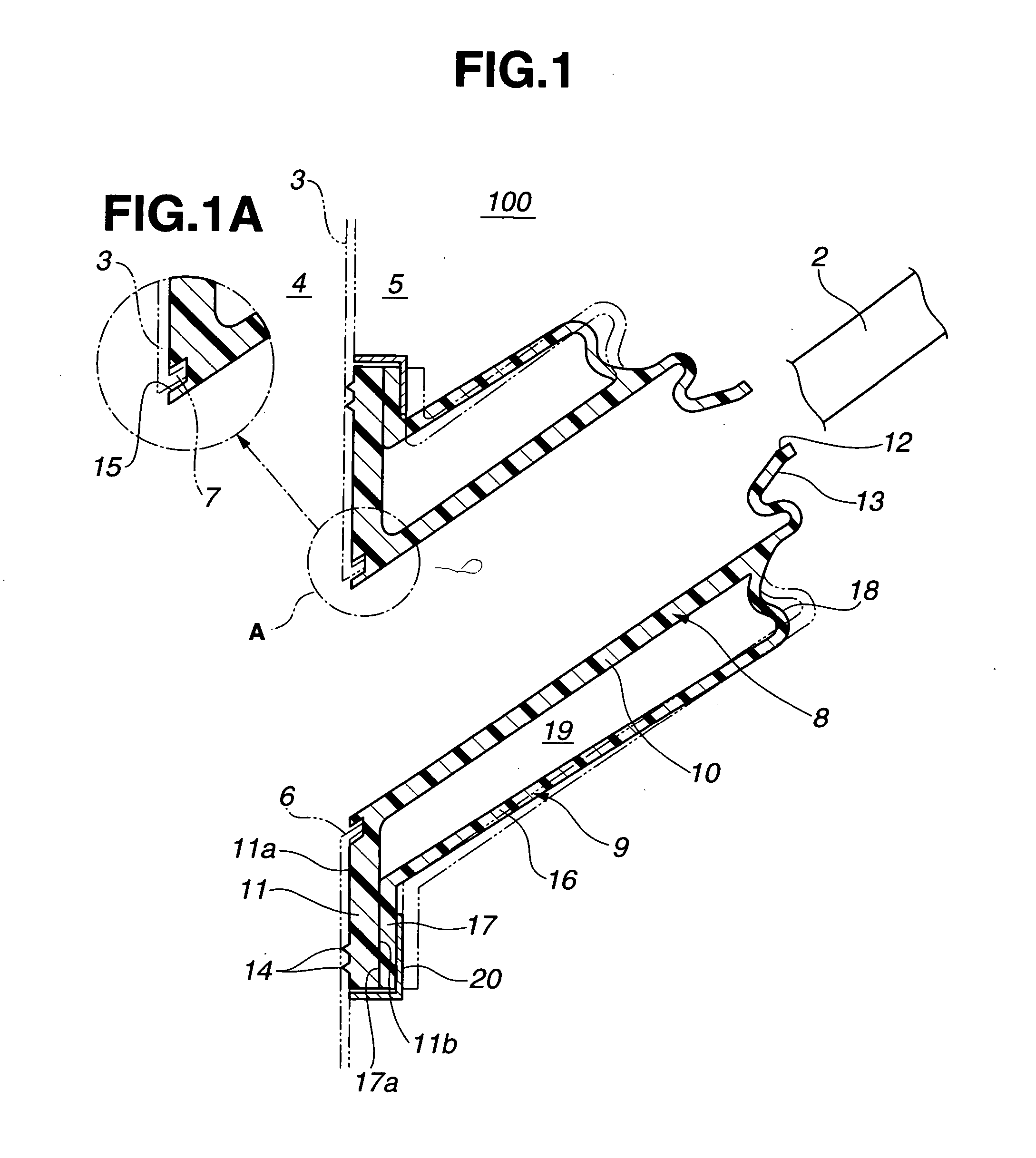
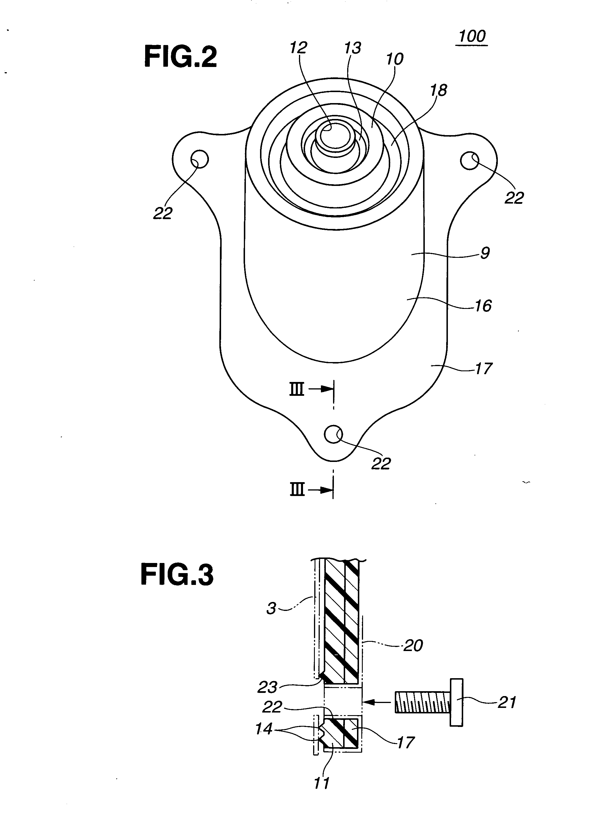
[0021] Referring to FIGS. 1 to 3 of the drawings, particularly FIGS. 1 and 2, there is shown a steering shaft boot or cover 100 which is the present invention.

[0022] As is best understood from FIG. 1, the steering shaft boot 100 is arranged aslant to support a steering shaft 2 while sealing a clearance defined between the steering shaft 2 and a dash panel 3 through which the steering shaft 2 passes.

[0023] The dash panel 3 is a partition panel installed between an engine room 4 and a passenger cabin 5, and has a steering shaft bore 6 through which the steering shaft 2 passes. As shown, the steering shaft bore 6 is defined by an annular ridge 7 bent back from a major part of the dash panel 3 toward the passenger cabin 5.

[0024] It is to be noted that the steering shaft boot 100 is a molded one-body member made of an elastic material and generally comprises an inner boot 8 that covers the steering shaft 2 and an outer boot portion 9 that covers the inner boot portion 8 leaving a cylin...

second embodiment

[0044] Referring to FIG. 4, there is shown a steering shaft boot 200 which is the present invention.

[0045] Since the boot 200 of this embodiment is similar to the above-mentioned boot 100 of the first embodiment, only parts or portions that are substantially different from those of the first embodiment 100 will be described in the following. The substantially same parts and portions as those of the first embodiment 100 are denoted by the same numerals and detailed explanation of such same parts and portions are omitted from the following description for simplification of the same.

[0046] As is seen from FIG. 4, in this second embodiment 200, a second upper wall portion 18A, a first flange portion 11A and a second flange portion 17A are different from the second upper wall portion 18, the first flange portion 11 and the second flange portion 17 of the first embodiment 100.

[0047] That is, as shown, the second upper wall portion 18A is shaped like a bellows. With this, the flexibility...

third embodiment

[0050] Referring to FIG. 5, there is partially shown a steering shaft boot 300 which is the present invention. It is to be noted that the part shown by this drawing is a portion that corresponds to the portion indicated by arrow “V” of FIG. 4.

[0051] Since the boot 300 of this embodiment is similar to the boot 200 of the second embodiment, only parts or portions that are substantially different from those of the second embodiment 200 will be described in the following.

[0052] As is seen from FIG. 5, in this third embodiment 300, first and second flange portions 11B and 17B are different from the first and second flange portions 11A and 17A of the second embodiment 200.

[0053] That is, as shown, the first flange portion 11B has a single stepped surface 42 and the second flange portion 17B has also a single stepped surface 43, and upon mating of the first and second flange portions 11B and 17B, these stepped surfaces 42 and 43 are intimately engaged with each other. Furthermore, in thi...


PUM


Abstract

A steering shaft boot of a molded elastic material comprises an inner boot portion including a first cylindrical portion that is adapted to cover a steering shaft, a first flange portion that extend radially outward from one axial end of the first cylindrical portion and is adapted to be secured to a panel member and a first upper wall portion that extends radially inward from the other axial end of the first cylindrical portion and is adapted to be put on an outer surface of the steering shaft; and an outer boot portion including a second cylindrical portion that covers the first cylindrical portion while keeping a certain clearance therebetween, a second flange portion that extends radially outward from one axis end of the second cylindrical portion and is adapted to be secured to the panel member and a second upper wall that extends radially inward from the other axial end of the second cylindrical portion to the other axial end of the first cylindrical portion. The first and second flange portions are separate members but engageable when in use.

Description

BACKGROUND OF THE INVENTION [0001] 1. Field of the Invention [0002] The present invention relates to automotive steering shaft boots or covers, and more particularly to the steering shaft boots of a type that elastically holds a steering shaft to a dash panel of the vehicle in a manner to seal a steering shaft bore of the dash panel through which the steering shaft passes. [0003] 2. Description of the Related Art [0004] Japanese Laid-open Patent Application (Tokkaihei) 8-198122 shows a steering shaft boot of the above-mentioned type. That is, the steering shaft boot of this published Application generally comprises a flange that is secured to a peripheral portion of the steering shaft bore of the dash panel, a holder that holds the steering shaft through a ball bearing, an inner rubber boot that extends from the flange to the holder and an outer rubber boot that also extends from the flange to the holder while covering the inner rubber boot. Due to provision of a so-called double la...

Claims


Application Information

Patent Timeline
Patent Type & Authority Applications(United States)
IPC IPC(8): F16D3/84
CPCB60R13/02B60R13/0206B60R13/06B62D1/16F16J3/041F16J3/042F16J15/52
Inventor TERASHIMA, KATSUYA
Owner KINUGAWA RUBBER IND CO LTD
Learn More