
Chemical vapor deposition of long vertically aligned dense carbon nanotube arrays by external control of catalyst composition

a technology of dense carbon nanotubes and catalysts, applied in vacuum evaporation coatings, chemical vapor deposition coatings, coatings, etc., can solve the problems of uncontrollable and cost effective growth methods for mass production of sufficiently pure cnts, widespread practical use of cnts, and undesirable side effects of cvd of cnts on al/fe/mo multilayer catalysts

Inactive Publication Date: 2006-09-07
UT BATTELLE LLC
View PDF3 Cites 51 Cited by
  • Summary
  • Abstract
  • Description
  • Claims
  • Application Information

AI Technical Summary

Benefits of technology

[0021] In another embodiment, a heatable CVD reactor that produces a carbon nanotube film on a catalyst layer is improved by adding apparatus that comprises an externally controllable sublimation source for delivering a catalyst precursor gas to the catalyst layer.

Problems solved by technology

The main hurdle that prevents widespread practical use of CNTs is the lack of controllable and cost effective growth methods for the mass production of sufficiently pure CNTs.
CVD of CNTs on Al / Fe / Mo multilayer catalysts suffers from undesirable side effects.
The first side effect is poor CNT growth.
Thickness control required to obtain such a precise catalyst composition is difficult to achieve using a simple evaporator.
The inadvertent variations in the thickness of the constituent layers manifest themselves in poor CNT growth leading to low CNT yields.
The second side effect is growth stoppage.
Both of these undesirable side effects are related to the composition of the catalyst layer, in particular to the content of the active iron catalyst.
The drawback of both of these techniques is that the amount of ferrocene cannot be controlled.
Consequently, overdosing of ferrocene occurs and the CNTs grown by these techniques have inferior properties.

Method used


Image

  • Chemical vapor deposition of long vertically aligned dense carbon nanotube arrays by external control of catalyst composition
  • Chemical vapor deposition of long vertically aligned dense carbon nanotube arrays by external control of catalyst composition
  • Chemical vapor deposition of long vertically aligned dense carbon nanotube arrays by external control of catalyst composition

Examples


Embodiment Construction

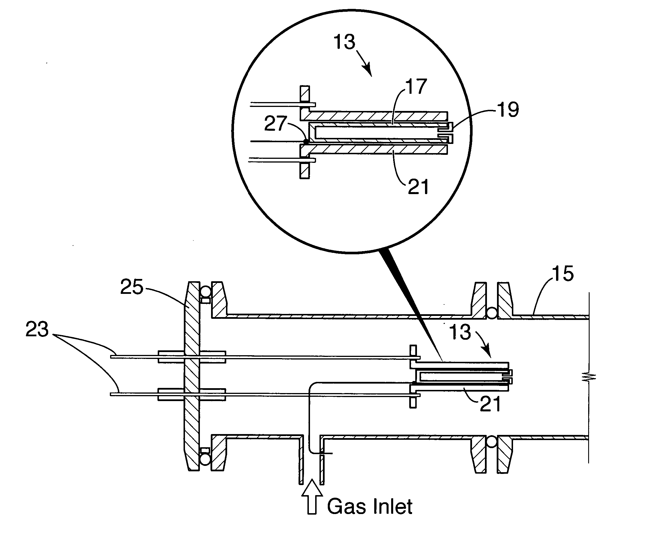
[0030] A method providing extra Fe from an externally-controlled ferrocene source and changing the catalyst composition during a CNT growth process is described. The Fe precursor is ferrocene, an organometallic molecule that upon decomposition releases one Fe atom per each molecule. Decomposition of ferrocene is induced by the metal catalyst layer and is highly surface-specific and selective. Selectivity means that CNT growth occurs only on the areas where the catalyst layer is present. The Fe atoms released by decomposition of ferrocene catalyze the decomposition of acetylene and enhance the growth of VACNTs.

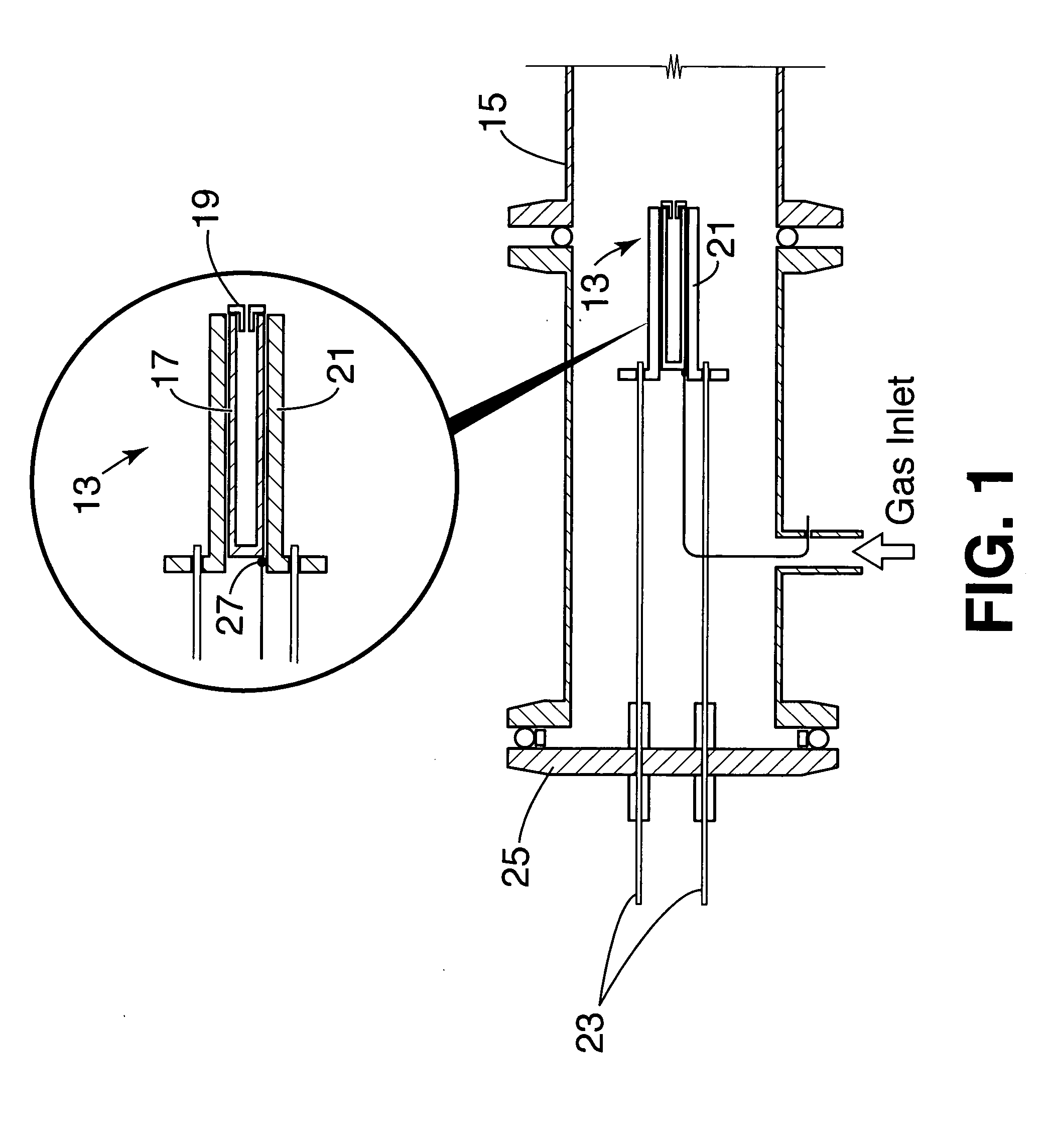
[0031]FIG. 1 illustrates the thermal evaporation source 13 for introducing ferrocene directly into the gas stream of a CVD CNT process. In FIG. 1, the ferrocene source 13 is located at the inlet 15 of a quartz tube furnace. The ferrocene is contained in a 0.22 in. diameter, 2 in. long tantalum cartridge 17. After being loaded with 200-300 mg of ferrocene, the open end of the c...


PUM

PropertyMeasurementUnit
Lengthaaaaaaaaaa
Lengthaaaaaaaaaa
Electrical conductoraaaaaaaaaa

Abstract

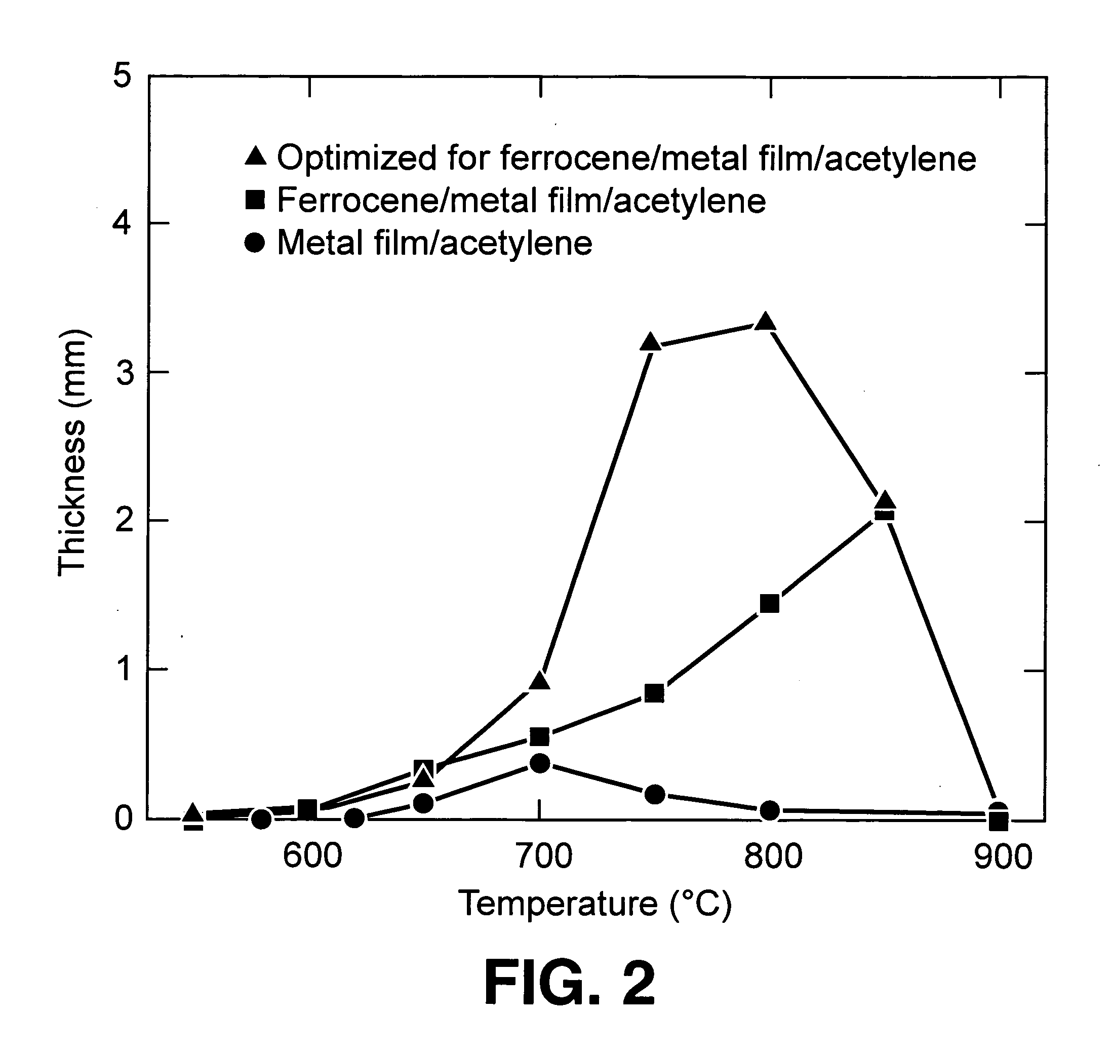
Vertically aligned carbon nanotubes (VACNTs) of increased length are produced in a method that introduces ferrocene into an acetylene / hydrogen / inert gas stream during a chemical vapor deposition process. The ferrocene is supplied from a controllable thermal sublimation source. Independent and precise control of the ferrocene into the feedstock gas facilitates the growth of thick films comprising long carbon nanotubes on conductive substrates. An order of magnitude increase in the length of CNTs, from a few hundred microns to several mm is achieved.

Description

STATEMENT REGARDING FEDERALLY SPONSORED RESEARCH OR DEVELOPMENT [0001] The United States Government has rights in this invention pursuant to Contract No. DE-AC05-00OR22725 between the United States Department of Energy and UT-Battelle, LLC.BACKGROUND OF THE INVENTION [0002] 1. Field of the Invention [0003] The present invention relates to the growth of vertically aligned carbon nanotube (VACNT) arrays on predeposited metal catalyst layers by the chemical vapor deposition (CVD) process. More particularly, longer CNTs and thicker CNT films are achieved through the use of a controllable ferrocene sublimator during the growth process. The sublimator acts as a secondary source of iron atoms, and provides significant control over the growth process. [0004] 2. Description of Prior Art [0005] Carbon nanotubes (CNTs) exhibit extraordinary physical properties that make them attractive for a wide range of novel applications from quantum electronic devices to superstrong composite materials. Th...

Claims


Application Information

Patent Timeline
IPC IPC(8): C23C16/00
CPCB82Y30/00C23C14/243C23C14/26C23C16/18
Inventor ERES, GYULA
Owner UT BATTELLE LLC
Learn More