
Selection method for data communication between base station and transponders

a data communication and base station technology, applied in transmission, sensing record carriers, wireless commuication services, etc., can solve the problems of reducing the range of data communication, high power consumption, and the transponder typically does not know these points in time, so as to preserve the structure of the data communication protocol, minimize the current consumption of the transponder, and optimize the data transmission rate

Inactive Publication Date: 2006-09-07
ATMEL GERMANY
View PDF17 Cites 4 Cited by
  • Summary
  • Abstract
  • Description
  • Claims
  • Application Information

AI Technical Summary

Benefits of technology

[0022] It is therefore an object of the present invention to provide data communication between a base station and transponder in which an optimal data transmission rate is ensured with the utilization of specified sidebands. A further object provides for at least two mutually distinguishable signals to be transmitted back by the transponder after reception and analysis of the query signal. A further object is to provide an easy-to-implement data communication between a base station and transponder that is not only usable worldwide but also minimizes the current consumption of the transponder while preserving the structure of the data communication protocol in particular.

Problems solved by technology

Technical implementation of multiple access in RFID systems places a number of demands on the transponders and base station, since it is necessary to reliably prevent the data returned by the transponders from colliding in the receiver of the base station and thereby becoming unreadable, without a significant expenditure of time.
However, the transponder typically does not yet know these points in time Tx at the beginning of a data communication or of the arbitration method.
However, this method has several disadvantages:
However, this entails a relatively high power consumption, which directly results in a correspondingly reduced range for the data communication in the case of passive transponders, for example.
The higher frequency of the two sidebands cannot be an even multiple of the respective lower frequency, as otherwise the harmonics will be more or less equal, and precise determination of the frequency of the sidebands by the base station is no longer possible as a result of multipath propagation and the associated constructive and destructive interference.
However, this is also accompanied by an increased current consumption by the transponder, which is to be avoided on account of the limited energy in the transponder and on account of the range.
An offset in the kilohertz range (up to 125 KHz) is permitted, but would significantly prolong the arbitration symbol, which would then undesirably lead to lower data transmission rates.
However, this results in significant modulation losses, which undesirably results in a reduction in the achievable range of the data communication between base station and transponder.
In addition, the data transmission rate is also relatively low on account of the HF regulations applicable in Europe.
However, this significantly reduces the data transmission rate, and thus the data transmission speed.
Such a long response time is too long for current RFID systems.
The aforementioned requirements of low current consumption, low oscillator frequency, and large oscillator tolerances cannot be satisfactorily met through the use of subcarrier modulation.

Method used


Image

  • Selection method for data communication between base station and transponders
  • Selection method for data communication between base station and transponders
  • Selection method for data communication between base station and transponders

Examples


Embodiment Construction

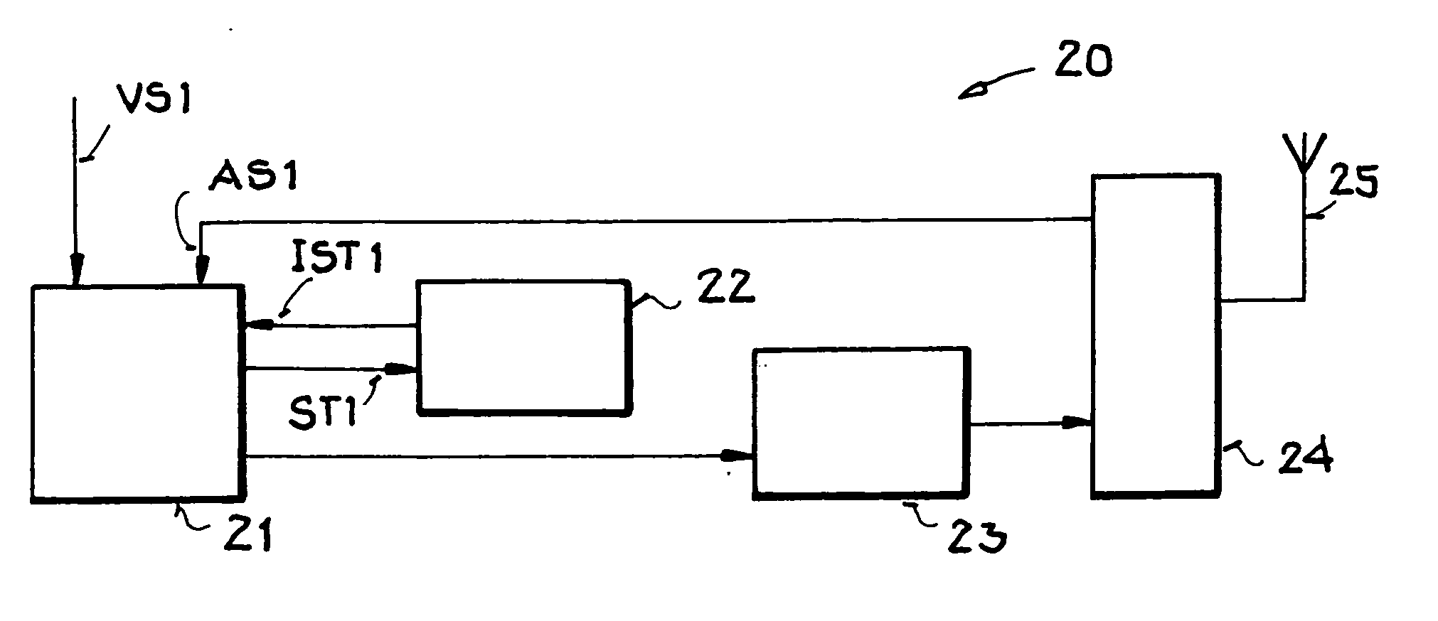
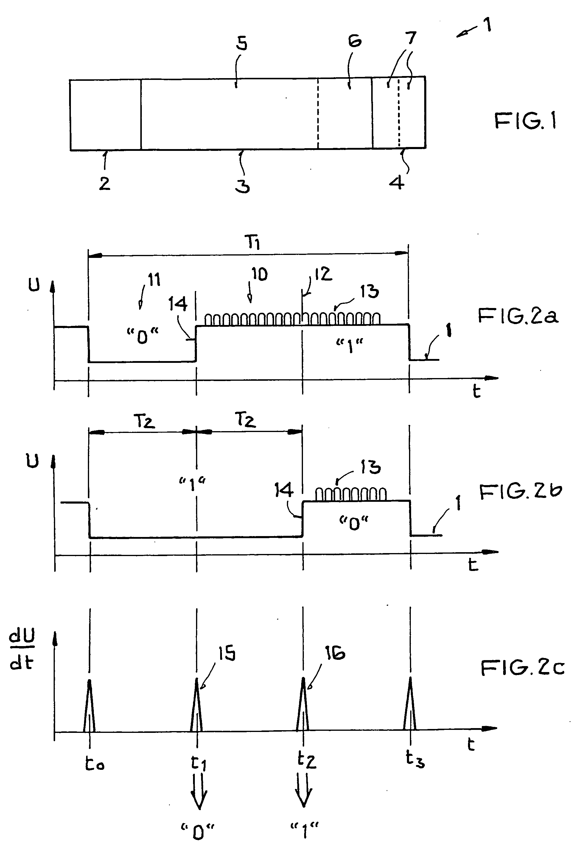
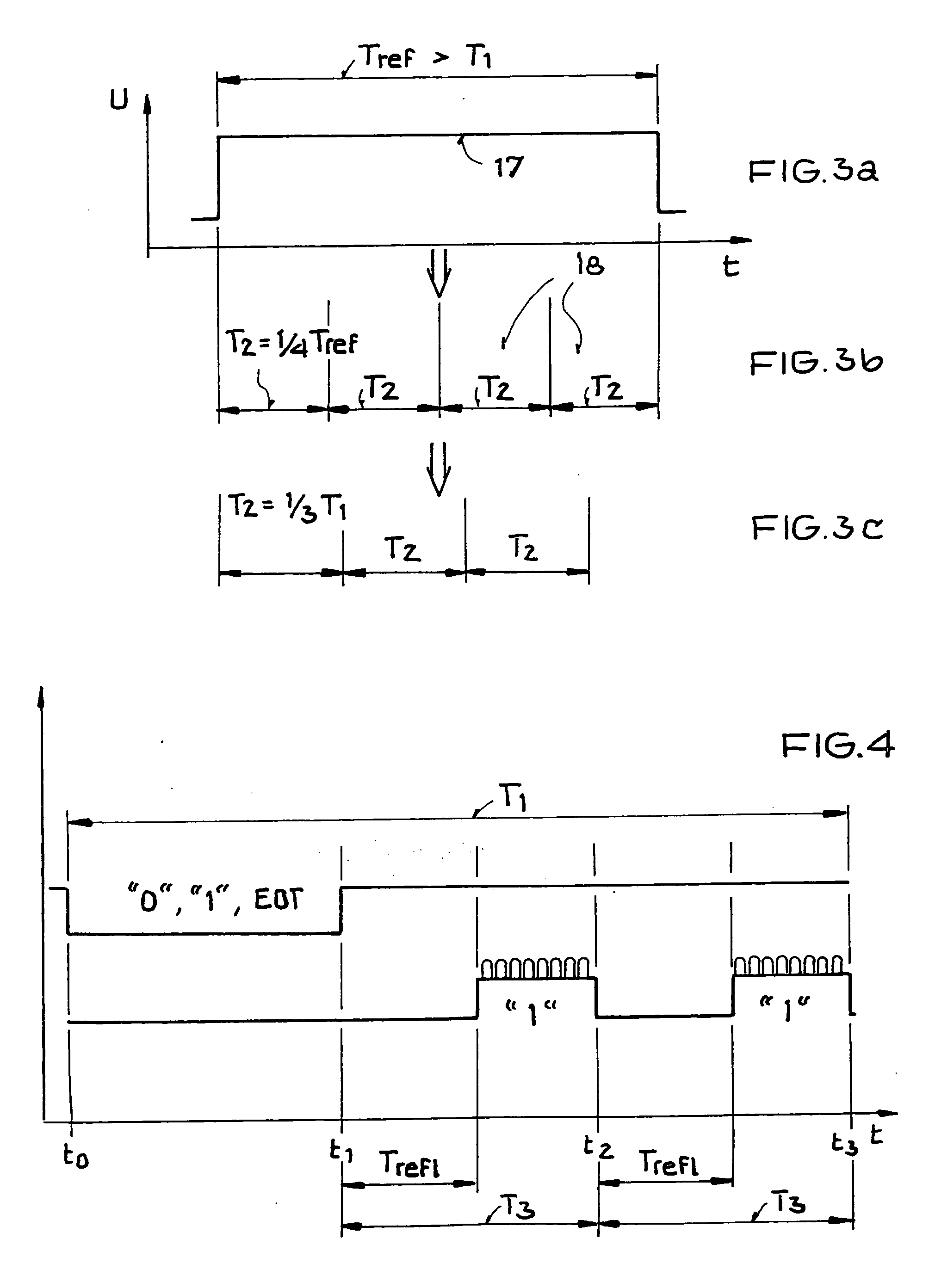
[0052] In the drawings, like or functionally like elements, data, and signals are identified with the same reference labels, unless otherwise specified. The representations in FIGS. 1-4, and 6 each relate to a time sequence of a given data communication.

[0053] Firstly, FIG. 1 shows a basic structure of an information packet 1 such as is used for data communication between a base station and a transponder.

[0054] The information packet 1 has a header section 2, a middle section 3, and a trailer section 4. The number of data items to be transmitted and their identification, and in many applications control information as well, are defined by the header section 2. In particular, the header section 2 defines reference times that are used for further data processing in the middle section 3 or data field 5. The middle section 3 contains the relevant data to be transmitted, wherein the middle section 3 can also preferably be used for purposes of control in some applications. The middle se...


PUM


Abstract

A selection method for selecting at least one transponder located in the response area of a base station, which are linked to one another by a wireless bidirectional data communication path, in which method the base station transmits an electromagnetic carrier signal, which has at least one arbitration symbol, wherein each arbitration symbol has a query segment in which data are encoded by the base station, and has a response segment that can be used by the transponder for coding and modulation of information for return data transmission, wherein the selection of a transponder takes place on the basis of distinguishable points in time in the time segment for the modulation that are produced from a reference time which is derived from the arbitration symbol itself.

Description

[0001] This nonprovisional application claims priority under 35 U.S.C. § 119(a) on German Patent Application No. DE 102005009765, which was filed in Germany on Mar. 3, 2005, and which is herein incorporated by reference. BACKGROUND OF THE INVENTION [0002] 1. Field of the Invention [0003] The present invention relates to a selection method for data communication between a base station and transponders. [0004] 2. Description of the Background Art [0005] The invention resides in the field of transponder technology and more particularly in the field of contactless communication for the purposes of identification. Although applicable in principle to any desired communication systems, the present invention and the problems it was designed to solve are explained below with respect to RFID communication systems and their applications. RFID stands for “Radio Frequency Identification.” For general background on RFID technology, please refer to the “RFID Handbuch” by Klaus Finkenzeller, Hanser...

Claims


Application Information

Patent Timeline
Patent Type & Authority Applications(United States)
IPC IPC(8): H04B7/005H04Q7/00
CPCG06K7/0008G06K7/10297G06K19/0723H04L5/143
Inventor FRIEDRICH, ULRICH
Owner ATMEL GERMANY
Learn More