
Method and system for proximity tracking-based adaptive power control of radio frequency identification (RFID) interrogators

a technology of proximity tracking and power control, applied in the field of proximity tracking based adaptive power control of radio frequency identification (rfid) interrogators, can solve the problems of neighboring reader transmission, interference between readers, and the rate and range at which an rfid reader identifies rfid tags can be severely compromised

Inactive Publication Date: 2006-09-07
IBM CORP
View PDF5 Cites 127 Cited by
  • Summary
  • Abstract
  • Description
  • Claims
  • Application Information

AI Technical Summary

Benefits of technology

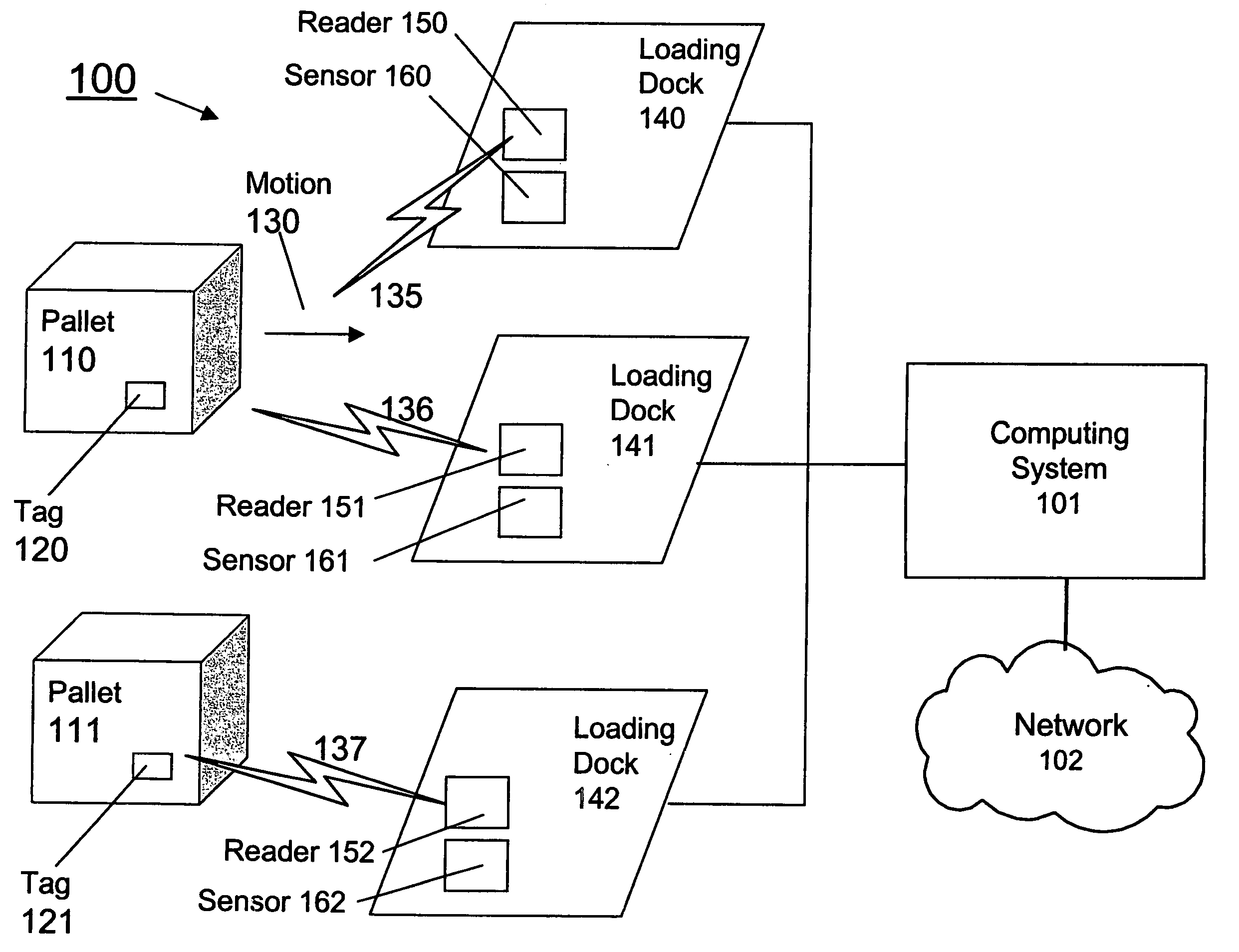
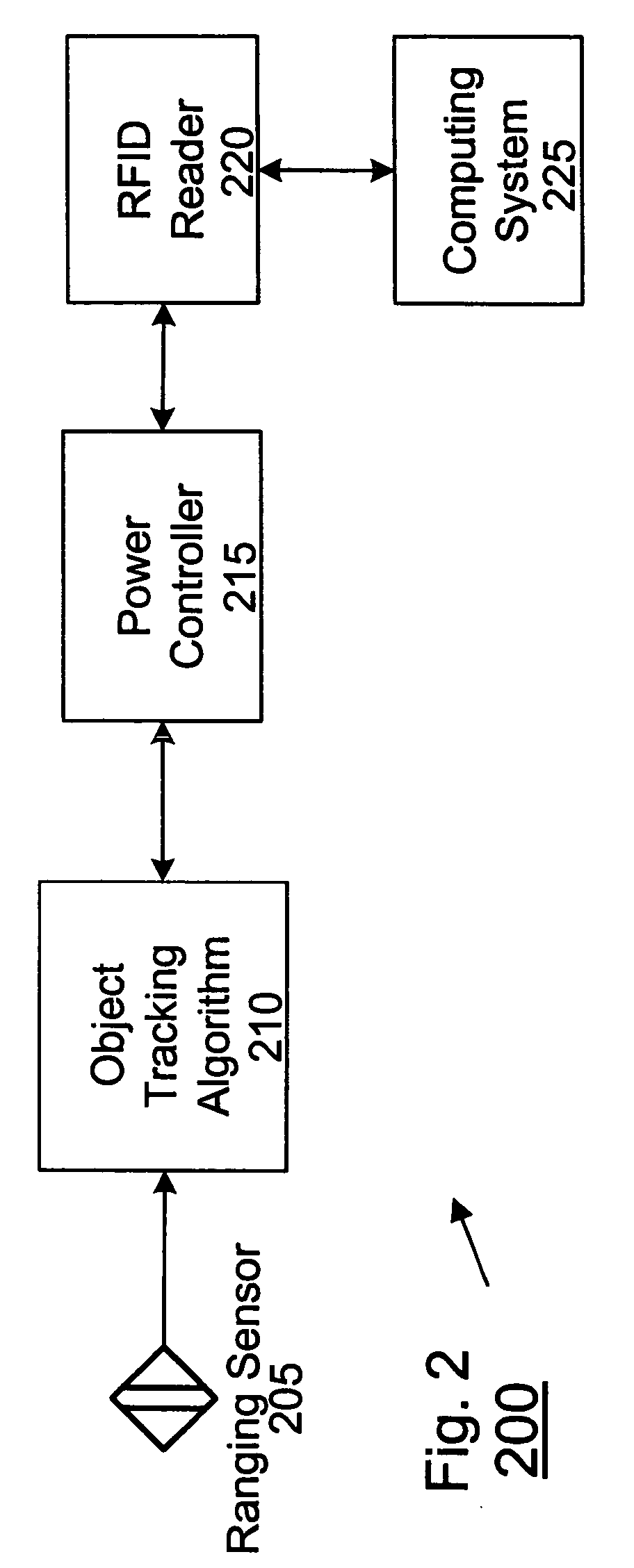
[0015] Thus, the present invention provides a low-complexity adaptive power control technique to mitigate interference in dense RFID reader configurations. This technique includes means to track a proximity parameter (e.g., the distance between the reader and the object that is labeled with an RFID tag such as, for example, a pallet), and a control algorithm that adjusts or varies the power level of the radiated antenna RF power of the reader in accordance with the measured distance to the object. For example, as the object moves closer to the reader, the radiated reader power can be reduced, thereby limiting the interference to neighboring readers.
[0019] In comparison to conventional solutions, the present invention can coexist with existing solutions (e.g., frequency hopping, etc.) and also can provide the useful artifact of determining additional information about the tagged object (e.g., the position of and the direction in which the object is moving, such as for example, leaving or entering a warehouse).

Problems solved by technology

In environments containing many Radio Frequency Identification Interrogators (henceforth referred to as “RFID readers”), the rate and range at which an RFID reader identifies RFID tags can be severely compromised by interference from neighboring reader transmissions.
Each loading dock may have many readers leading to interference between readers for the same, adjacent, nearby loading docks.
The interference problem for adjacent and nearby check-out lanes is then similar to the loading dock problem described above.
This interference occurs when two or more neighboring readers transmit simultaneously or when responses from RFID tags collide with neighboring reader transmissions.
Furthermore, all of these techniques require significant added complexity to manage and coordinate time slot, frequency slot, or hopping pattern assignments.
Frequency hopping becomes increasingly ineffective for avoiding interference as the number of readers approaches the number of frequency slots available for hopping.
This helps to satisfy regulatory requirements on duty cycle, but does not address the interference problem if multiple readers must be used simultaneously.

Method used


Image

  • Method and system for proximity tracking-based adaptive power control of radio frequency identification (RFID) interrogators
  • Method and system for proximity tracking-based adaptive power control of radio frequency identification (RFID) interrogators
  • Method and system for proximity tracking-based adaptive power control of radio frequency identification (RFID) interrogators

Examples


Embodiment Construction

[0025] Referring now to the drawings, and more particularly to FIGS. 1-4, there are shown exemplary embodiments of the method and structures according to the present invention.

Exemplary Embodiment

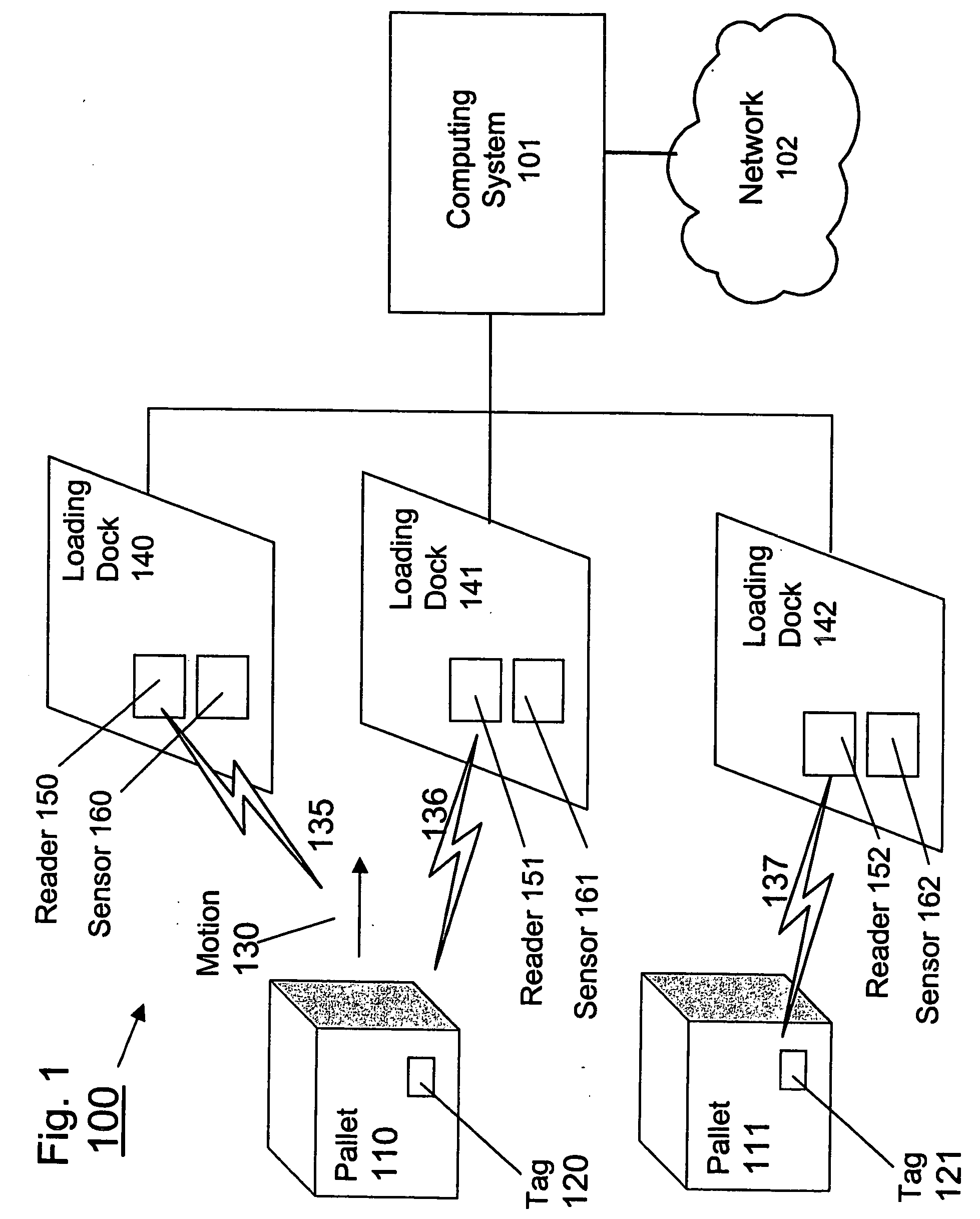
[0026] An RFID system 100 that implements the invention is shown in FIG. 1. System 100 illustrates the invention for an exemplary application of a supply chain distribution center where many loading dock doors may be arrayed next to one another.

[0027] As would be evident to one of ordinary skill in the art taking the present application as a whole, the invention is not limited to this application and indeed can be practiced in many different environments and applications. For example, the invention may similarly be employed for a retail store point-of-sale check-out system, for an electronic toll collection system, for a customer service counter, etc. For the last three examples, the tagged objects may be retail items, vehicles, or people, respectively.

[0028]FIG. 1 depicts a series of l...


PUM


Abstract

A radio frequency identification (RFID) system (and method), includes at least one RFID reader to read at least one RFID tag, a sensor for determining a proximity parameter for the at least one tag with respect to the at least one reader, and a controller that controls the RF power of the at least one reader.

Description

BACKGROUND OF THE INVENTION [0001] 1. Field of the Invention [0002] The present invention generally relates to a method and system for power control of radio frequency identification (RFID) interrogators, e.g., readers, and more particularly to a method and system for proximity tracking based adaptive power control of RFID interrogators. [0003] 2. Description of the Related Art [0004] RFID is a technology that employs tags (e.g., wireless radio transponders), attached to a material or object. The tag sends information stored on the tag in response to a radio signal from a reader, which reads the information and forwards it to other systems for subsequent processing. Passive tags do not include transmitters, but send their information as they reflect the radio signal received from the reader back to the reader. [0005] Typically, in logistics applications, tags are attached to materials or objects and detected by fixed readers in order to support automated material identification and ...

Claims


Application Information

Patent Timeline
IPC IPC(8): H04Q5/22
CPCG06K7/0008G06K7/10128G06K7/10356G06K19/0701
Inventor HILD, STEFAN G.MOSKOWITZ, PAUL A.REASON, JOHNATHAN M.
Owner IBM CORP
Learn More