
Septic tank

a technology for septic tanks and sludge, applied in the field of septic tanks, can solve the problems of sludge providing the environment for growth and propagation of nitrobacteria, affecting the effect of decomposition and filtration, and affecting the effect of stirring and fast recycling, so as to prevent suspension and deposits

Inactive Publication Date: 2006-09-07
LIAO CHIN TUAN
View PDF46 Cites 13 Cited by
  • Summary
  • Abstract
  • Description
  • Claims
  • Application Information

AI Technical Summary

Benefits of technology

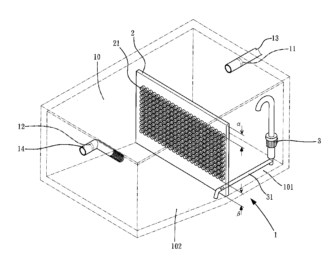
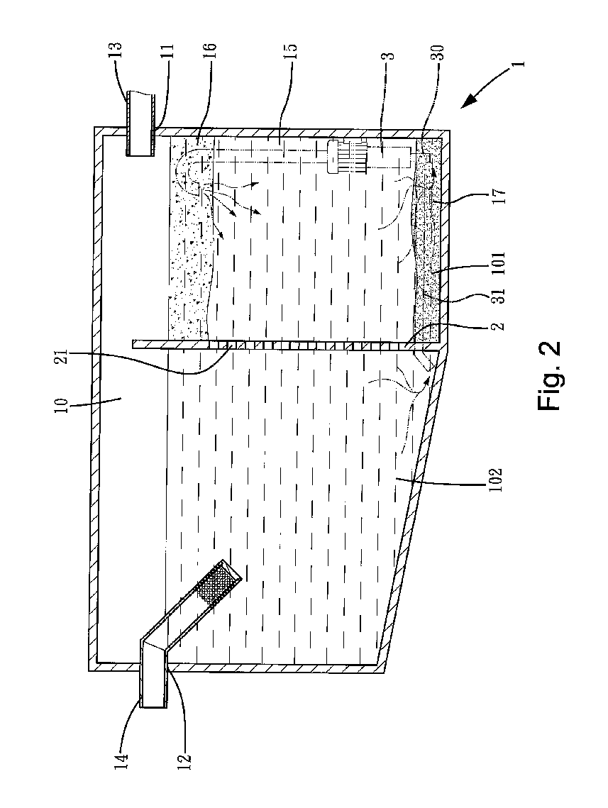
[0008] The partitioning member prevents suspensions and deposits in the first subchamber from entering the second subchamber. Preferably, the partitioning member comprises an upper blocking area for preventing the suspensions in the first subchamber from entering the second subchamber and a lower blocking area for preventing the deposits in the first subchamber from entering the second subchamber, with the through-holes being defined in an intermediate portion of the partitioning member.

Problems solved by technology

However, the stirring or recycling procedure would destroy the environment for the nitrobacteria.
Further, stirring and fast recycling would adversely affect the effect of decomposition and filtration, failing to purify the waste water.
As a result, the sludge providing the environment for growth and propagation of the nitrobacteria could not effectively gather and deposit.
Further, the water discharged from the septic tank is not clear enough.

Method used


Image

  • Septic tank
  • Septic tank
  • Septic tank

Examples


Embodiment Construction

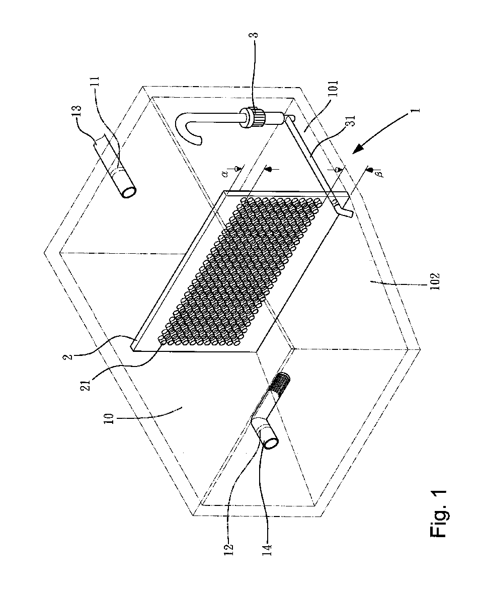
[0027]FIGS. 1 and 2 show an embodiment of a septic tank in accordance with the present invention. The septic tank comprises a chamber 10, a waste water inlet 11 to which an inlet pipe 13 is mounted, and a waste water outlet 12 to which an outlet pipe 14 is mounted. A partitioning member 2 is mounted in the chamber 10 and separates the chamber 10 into a first subchamber 101 adjacent to the waste water inlet 11 and a second subchamber 102 adjacent to the waste water outlet 12. The outlet 12 is preferably two (2) inches lower than the inlet 11.

[0028] The outlet pipe 14 can be of a structure similar to that disclosed in U.S. patent application Ser. No. 10 / 931,743, the content of which is incorporated herein for reference. A submersible pump 3 is mounted in the first subchamber 101, which will be described in detail later. The partitioning member 2 includes a plurality of through-holes 21 in an intermediate portion thereof, allowing communication between the first subchamber 101 and the...


PUM

PropertyMeasurementUnit
Angleaaaaaaaaaa
Currentaaaaaaaaaa
Circumferenceaaaaaaaaaa

Abstract

A septic tank includes a chamber, an inlet through which waste water enters the chamber, an outlet, and an outlet pipe mounted to the outlet. At least one partitioning member is mounted in the chamber and separates the chamber into at least a first subchamber adjacent to the inlet and a second subchamber adjacent to the outlet. The partitioning member includes a plurality of through-holes allowing communication between the first subchamber and the second subchamber. The partitioning member prevents the suspensions and deposits in the first subchamber from entering the second subchamber. A submersible pump may be mounted in the first subchamber for creating recycling currents.

Description

CROSS REFERENCE TO RELATED APPLICATION [0001] This is a continuation-in-part application of U.S. patent application Ser. No. 10 / 931,743 filed Sep. 1, 2004. BACKGROUND OF THE INVENTION [0002] 1. Field of the Invention [0003] The present invention relates to a septic tank. More specifically, the present invention relates to a septic tank for treating household waste water including human feces in daily life. [0004] 2. Description of the Related Art [0005] Household waste water containing human feces is firstly collected in a septic tank in a basement of a building. Cleaner waste water after purification is discharged to adjacent water discharge pipes to avoid contamination to drinking water and the environment. The decayed and deposited sludge in the septic tank is removed when it is accumulated to a certain amount. [0006] Organic nitrogen in the septic tank is decomposed by nitrobacteria into ammonia, which is then oxidized into nitrate that is less toxic. The amount of organic nitro...

Claims


Application Information

Patent Timeline
IPC IPC(8): B01D21/02
CPCB01D21/0012B01D21/0018B01D21/0033B01D21/0036B01D21/02B01D2221/02B01D21/0039
Inventor LIAO, CHIN-TUAN
Owner LIAO CHIN TUAN
Learn More