
Method and apparatus for estimating distance to or from a geological target while drilling or logging

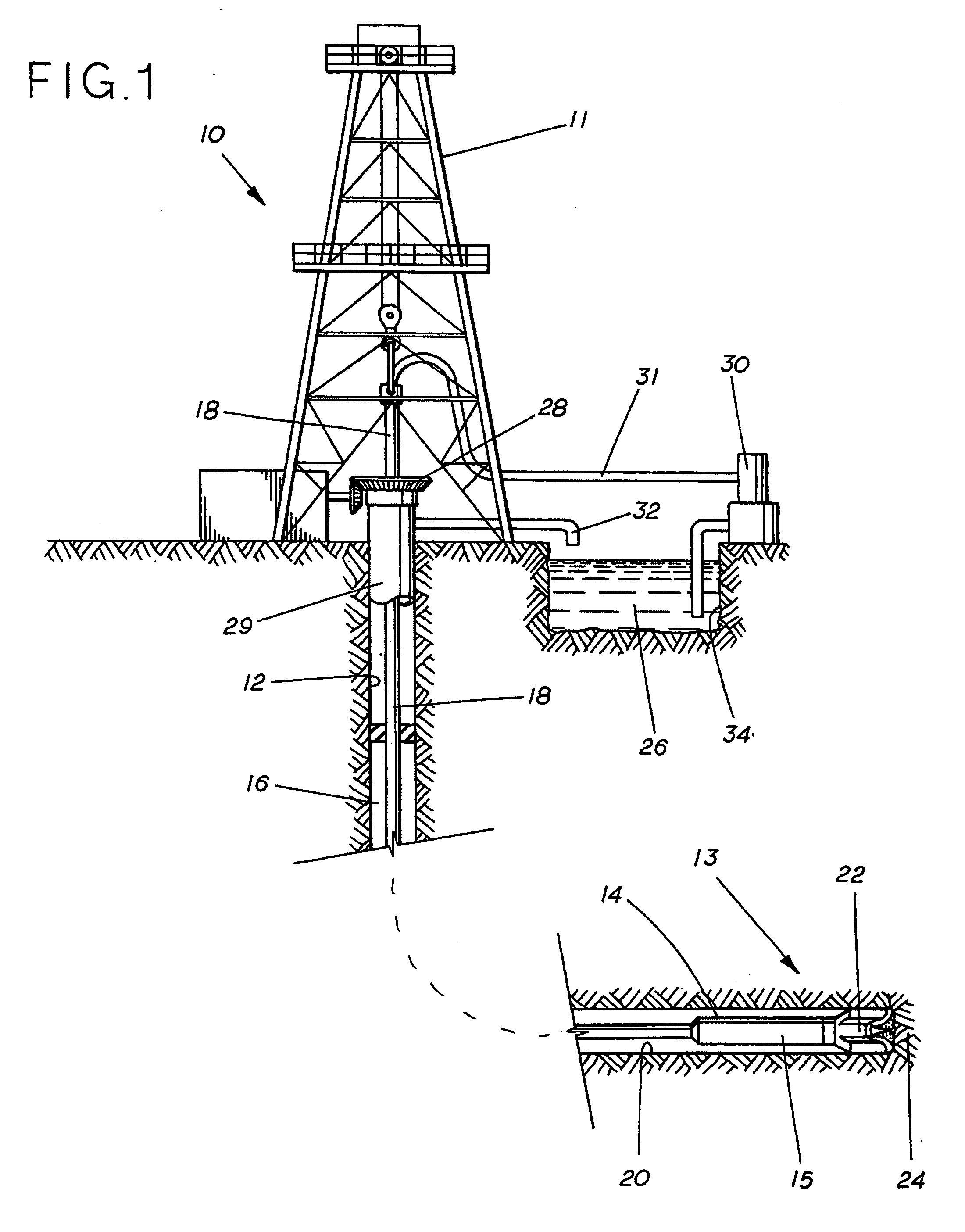
a geological target and distance estimation technology, applied in the field of hydrocarbon exploration and production, can solve the problems of providing little or no quantitative estimates of the distance of the wellbore, the wellbore exiting or missing the target, and the problem is even more pronounced for smaller targets

Active Publication Date: 2006-08-31
HALLIBURTON ENERGY SERVICES INC
View PDF12 Cites 34 Cited by
  • Summary
  • Abstract
  • Description
  • Claims
  • Application Information

AI Technical Summary

Benefits of technology

The patent text describes a problem in the oil and gas industry related to the difficulty of accurately detecting the distance of a borehole from certain geological features, such as oil-water contact boundaries. The prior art methods relied on conventional logging devices, which provided little or no quantitative estimates of the distance. This resulted in the driller's main concern being the oil-water contact boundary rather than other boundary strata on the sides of or above the producing zone, which may have been missed. The technical effect of this invention is to provide a better method for detecting the approach of boundary strata, especially while drilling horizontal wells, which will result in greater reliability and dependability of operation.

Problems solved by technology

Due to geological and petrophysical complexities, relying purely on the measurements from conventional logging devices provides little or no quantitative estimates of the distance of the wellbore from features of interest.
This can result in the wellbore exiting or missing the targets that have been determined for the wellbore.
This problem is even more pronounced for smaller targets.
In fact, if the motor type drilling assembly is being used, due to the occasional necessity to change the direction of the bit, a tool with a directionally focused sensor may be focused in the wrong direction to indicate the approach of an oil-water contact boundary stratum and therefore be unreliable.
Moreover, the need to reorient the tool may create undesirable drilling operations.
At one time, the prior art provided no effective or acceptable method for calculating the approximate angle or dip of an approaching boundary stratum, even though it was recognized that such information would generally be useful to the driller for various reasons.
In particular, while the prior art includes examples of techniques useful for determining, to some degree of approximation, relative proximity of a borehole to a geophysical boundary, there have not been shown effective means or methods for quantifying the distance between a borehole and a geophysical boundary.

Method used


Image

  • Method and apparatus for estimating distance to or from a geological target while drilling or logging
  • Method and apparatus for estimating distance to or from a geological target while drilling or logging
  • Method and apparatus for estimating distance to or from a geological target while drilling or logging

Examples


Embodiment Construction

[0019] In the disclosure that follows, in the interest of clarity, not all features of actual implementations are described. It will of course be appreciated that in the development of any such actual implementation, as in any such project, numerous engineering and technical decisions must be made to achieve the developers' specific goals and subgoals (e.g., compliance with system and technical constraints), which will vary from one implementation to another. Moreover, attention will necessarily be paid to proper engineering and programming practices for the environment in question. It will be appreciated that such a development effort might be complex and time-consuming, but would nevertheless be a routine undertaking for those of ordinary skill in the relevant fields.

[0020] Furthermore, for the purposes of the present disclosure, the terms “comprise” and “comprising” shall be interpreted in an inclusive, non-limiting sense, recognizing that an element or method step said to “comp...


PUM


Abstract

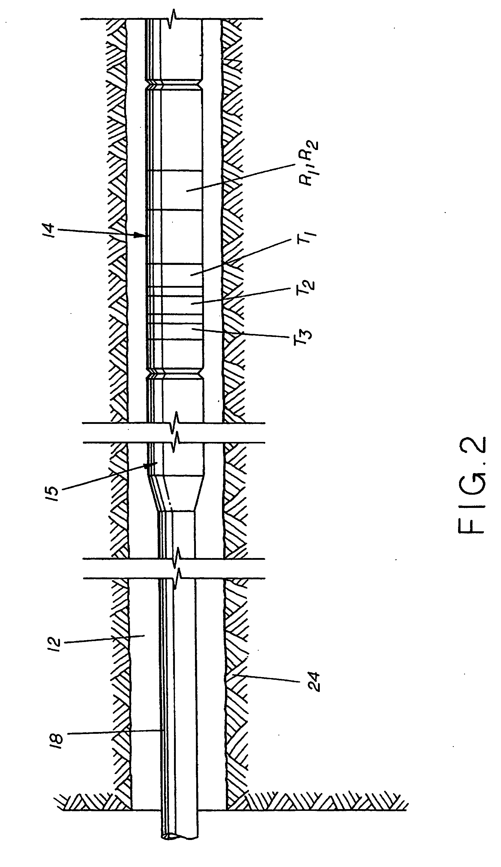
A system and method for estimating the distance between a borehole and a subsurface boundary of interest in a geophysical region. In one embodiment, available existing sensor data for the geophysical region is used to create a resistivity model of the region, with the model reflecting changes in resistivity across the boundary. A hypothetical borehole is defined in the model, with the hypothetical borehole having a number of segments along its length that are spaced-apart from the boundary by a number of different, preselected distances. Based on the existing data, resistivity curves corresponding to the hypothetical boundary are plotted. The ratio between two selected resistivity curves in each of the respective spaced-apart segments is computed, and these ratio values are plotted as a function of distance from the boundary. A curve-fitting algorithm is applied to the ratio plot to derive an equation which correlates the selected sensor readings with distance from the boundary. This equation may then be applied to actual sensor data from a sensor package present during an actual drilling operation to provide the drilling operator with quantified estimates of distance from an actual borehole and the boundary.

Description

FIELD OF THE INVENTION [0001] This invention relates generally to the field of hydrocarbon exploration and production, and more particularly relates to the surveying of boreholes. BACKGROUND OF THE INVENTION [0002] In hydrocarbon exploration and production, for a wellbore to be deemed successful, it is important for the operator to have knowledge of exactly how far the wellbore is from certain geological features of interest, either above or below the wellbore itself. [0003] Due to geological and petrophysical complexities, relying purely on the measurements from conventional logging devices provides little or no quantitative estimates of the distance of the wellbore from features of interest. This can result in the wellbore exiting or missing the targets that have been determined for the wellbore. This problem is even more pronounced for smaller targets. [0004] In recent years, there has been a substantial increase in the drilling of “horizontal” wells. Such wells often have much g...

Claims


Application Information

Patent Timeline
Patent Type & Authority Applications(United States)
IPC IPC(8): G06F19/00
CPCE21B7/046E21B47/022E21B47/026
Inventor GALIL EL ASKARY, SAID ABDEL
Owner HALLIBURTON ENERGY SERVICES INC
Learn More