Zoom lens and information device including the same
a technology of information device and zoom lens, which is applied in the direction of optics, instruments, optics, etc., can solve the problems of reducing the magnification power the length of the lens, and the restriction of the movement range of the third lens group, so as to reduce the quantity of light, the diameter of the aperture stop, and the effect of reducing the quantity of ligh
- Summary
- Abstract
- Description
- Claims
- Application Information
AI Technical Summary
Benefits of technology
Problems solved by technology
Method used
Image

Examples
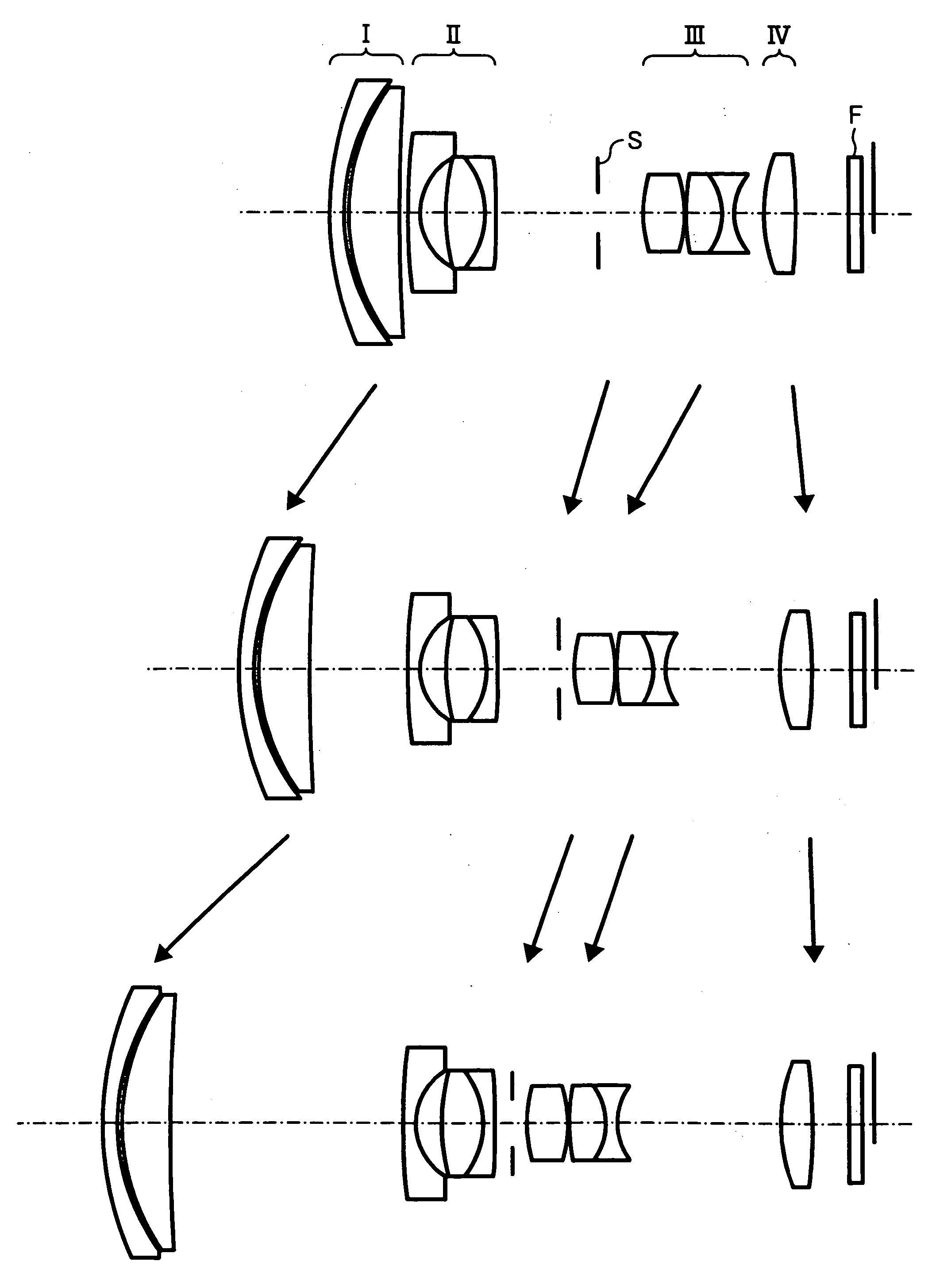
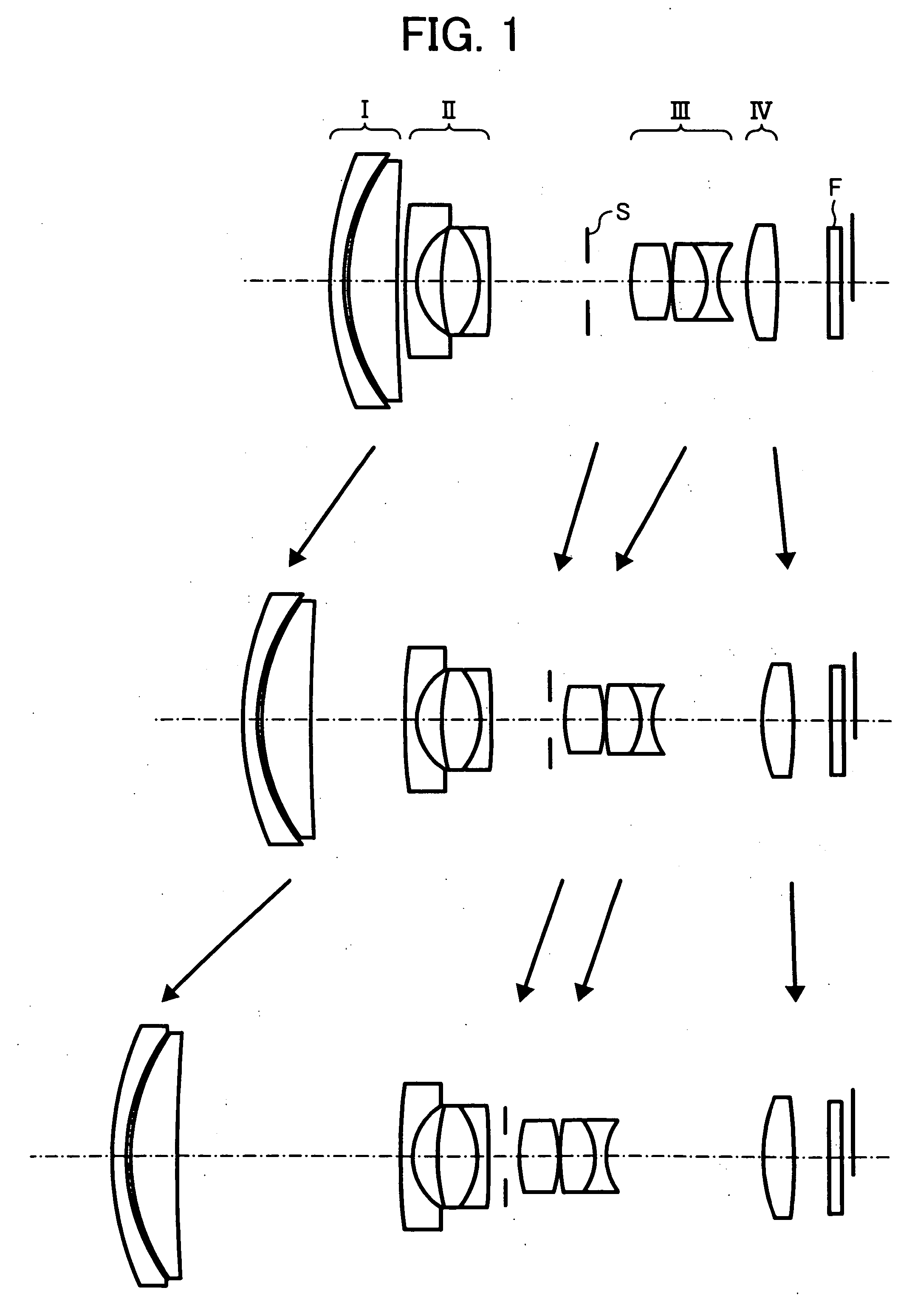
first embodiment
[0100] f=4.74˜21.59, F=3.32˜4.98, ω=39.14˜9.55
Surface No.RDNdνdnotes0123.3301.001.8466623.80First lens0215.0020.260315.4423.471.7725049.60Second lens04135.649variable(A)05*91.4460.841.8348142.70Third lens064.4391.770715.7042.671.7407727.80Fourth lens08−6.2050.741.8348142.70Fifth lens09*632.018variable(B)10Aperturevariable(C)stop11*8.3332.781.5891361.15Sixth lens12*−8.6070.101315.5882.421.8348142.70Seventh lens14−4.6910.801.6989530.10Eighth lens154.498variable(D)16*12.5002.211.5434056.00Ninth lens17−34.711variable(E)18∞0.901.5168064.20Filter(various)19∞
[0101] In the above table each of the lens surfaces represented by a surface number to which “*” (asterisk) is attached is a aspheric surface, and the same representations are used for describing other embodiments.
Aspheric Surface
Fifth Surface:
[0102] K=0.0, A4=2.42400×10⁻⁴, A6=−2.92208×10⁻⁶, A8=9.40210×10⁻⁹, A10=−4.16456×10⁻¹¹
Ninth Surface: [0103] K=0.0, A4=−5.16761×10⁻⁴, A6=1.81605×10⁻⁶, A8=−1.01642×10⁻⁶, A10=−1.75699×10⁻⁸
El...
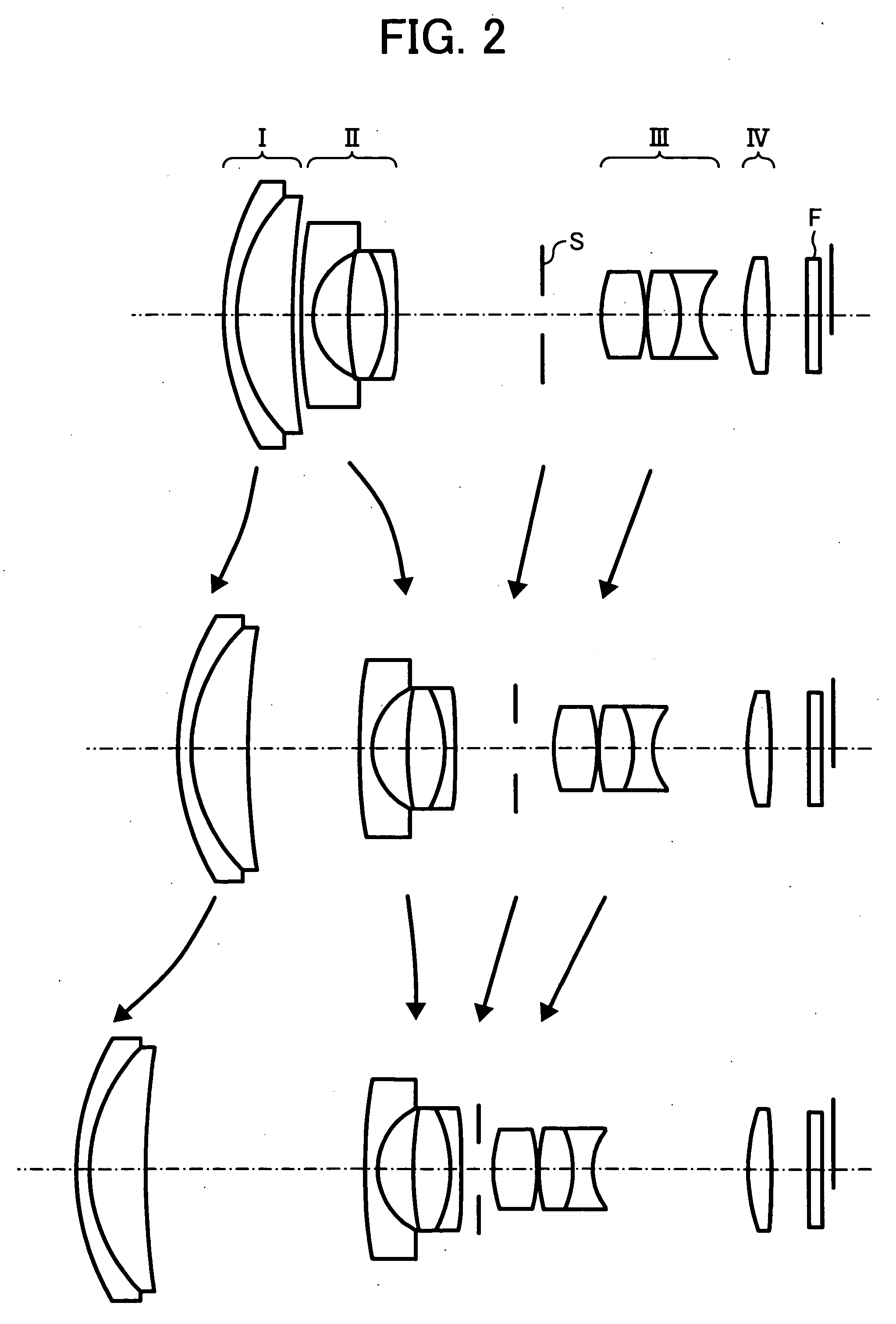
second embodiment
[0116] f=4.74˜21.55, F=3.61˜4.80, ω=39.16˜9.64
Surface No.RDNdνdnotes0118.5650.901.9228620.88First lens0212.1943.901.7234237.99Second lens0358.393variable(A)04*70.5010.841.8350042.98Third lens054.8592.420624.2192.541.7618226.61Fourth lens07−9.5290.741.8350042.98Fifth lens08*−247.508variable(B)09Aperturevariable(C)stop10*8.3333.011.5891361.25Sixth lens11*−10.3760.101212.4202.341.7550052.32Seventh lens13−7.1111.351.6889331.16Eighth lens144.591variable(D)15*13.6311.661.5891361.25Ninth lens16−45.606variable(E)17∞0.901.5168064.20Filter(various)18∞
Aspheric Surface
Fourth Surface: [0117] K=0.0, A4=1.78565×10⁻⁴, A6=−1.75390×10⁻⁶, A8=6.61261×10⁻⁹, A10=1.23143×10⁻¹¹
Eighth Surface: [0118] K=0.0, A4=−3.04000×10⁻⁴, A6=−7.18126×10⁻⁶, A8=1.05398×10⁻⁷, A10=−2.21354×10⁻⁸
Tenth Surface [0119] K=0.0, A4=−6.40609×10⁻⁴, A6=−7.03343×10⁻⁶, A8=8.98513×10⁻⁷, A10=−9.73391×10⁻⁸
Eleventh Surface [0120] K=0.0, A4=2.20124×10⁻⁴, A6=−8.24086×10⁻⁶, A8=1.09927×10⁻⁶, A10=−1.05069×10⁻⁷
Fifteenth Surface [0121] ...
third embodiment
[0131] f=4.74˜21.67, F=3.46˜4.91, ω=39.15˜9.50
Surface No.RDNdνdnotes0188.9200.901.8466623.78First lens0227.7762.671.7725049.62Second lens03−397.8620.100419.6831.791.7725049.62Third lens0537.587variable (A)06*19.0210.791.8350042.98Fourth lens073.7652.1108∞1.661.8466623.78Fifth lens09−7.9040.641.8042046.50Sixth lens10*−76.544variable (B)11Aperturevariable (C)stop12*8.6743.651.5891361.25Seventh lens13*−8.1320.101414.3312.431.7550052.32Eighth lens15−6.4590.801.6989530.05Ninth lens165.298variable (D)17*12.5001.841.5434056.00Tenth lens18−40.435variable (E)19∞0.901.5168064.20Filter(various)20∞
Aspheric Surface
Sixth Surface: [0132] K=0.0, A4=−1.22579×10⁻⁴, A6=−2.98179×10⁻⁷, A8=−1.93092×10⁻⁸, A10=−3.32554×10⁻¹⁰
Tenth Surface: [0133] K=0.0, A4=−8.28512×10⁻⁴, A6=−1.82812×10⁻⁵, A8=8.50623×10⁻⁸, A10=−1.90374×10⁻⁷
Twelfth Surface: [0134] K=0.0, A4=−8.08852×10⁻⁴, A6=1.58812×10⁻⁵, A8=−1.00403×10⁻⁶, A10=−2.75151×10⁻⁸
Thirteenth Surface: [0135] K=0.0, A4=4.07275×10⁻⁴, A6=−7.86358×10⁻⁶, A8=1.605...
PUM
 Abstract
Description
Claims
Application Information
 - R&D
- Intellectual Property
- Life Sciences
- Materials
- Tech Scout
- Unparalleled Data Quality
- Higher Quality Content
- 60% Fewer Hallucinations
Browse by: Latest US Patents, China's latest patents, Technical Efficacy Thesaurus, Application Domain, Technology Topic, Popular Technical Reports.
© 2025 PatSnap. All rights reserved.Legal|Privacy policy|Modern Slavery Act Transparency Statement|Sitemap|About US| Contact US: help@patsnap.com