
Actuation apparatus for power tool

a technology of actuation apparatus and power tool, which is applied in the direction of electrical apparatus, portable percussive tools, construction, etc., can solve the problems of high manufacturing cost of hammers and easy wear and tear, and achieve the effect of better grip

Inactive Publication Date: 2006-08-24
BLACK & DECKER INC
View PDF11 Cites 39 Cited by
  • Summary
  • Abstract
  • Description
  • Claims
  • Application Information

AI Technical Summary

Benefits of technology

[0010] By providing control means for controlling operation of the motor in response to at least one said signal, such that in at least one first predetermined mode of operation of said tool, said motor is operated by a first depression of the trigger and remains activated until deactivated by a second depression of the trigger, and in at least one second predetermined mode of operation of said tool, said motor is only activated while the trigger is depressed, this provides the advantage that the need for a mechanical detent system to latch on the trigger mechanism when a predetermined mode of operation is selected is eliminated. This is advantageous because an electronic system is not subject to mechanical wear and tear to the same extent as a mechanical system and can also be made much more compact, thus reducing the dimensions of the tool. Also, the apparatus can be manufactured more cost-effectively than apparatus incorporating a purely mechanical actuator system.
[0012] This provides the advantage that the operator does not have to continuously grip the trigger during the hammer mode operation of the tool, and therefore can move their hands around the body of the tool whilst it is in operation to provide a better grip.

Problems solved by technology

The electric combination hammer of GB2314288 suffers from the drawback that the components for the detent system are mechanical in nature, comprising cam surfaces and resilient springs, such that they are susceptible to wear and tear with repeated use.
Also, the use of such mechanical components makes the hammer expensive to manufacture.

Method used


Image

  • Actuation apparatus for power tool
  • Actuation apparatus for power tool
  • Actuation apparatus for power tool

Examples


Embodiment Construction

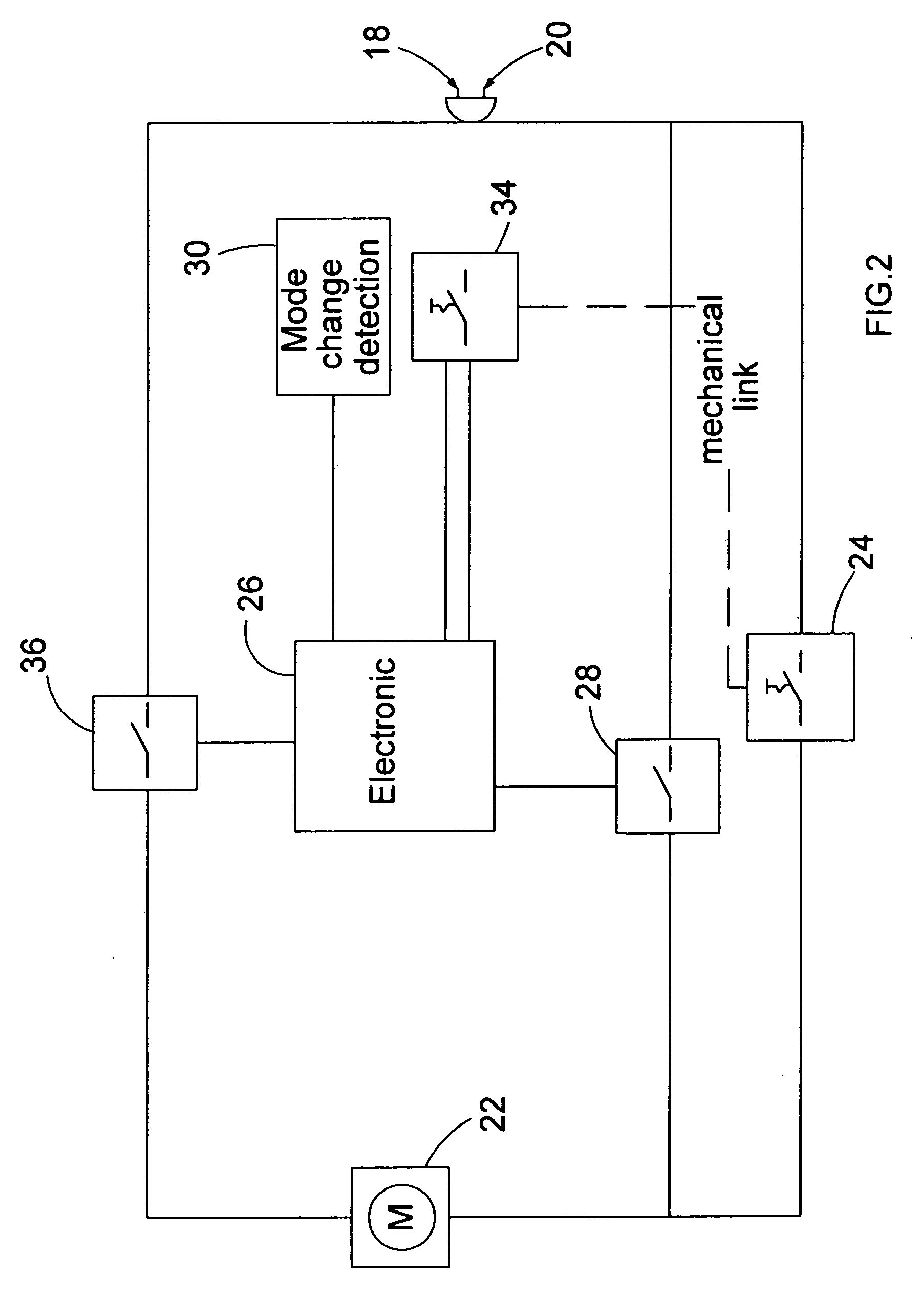
[0027] The first embodiment of the present invention will now be described with reference to FIGS. 1 and 2.

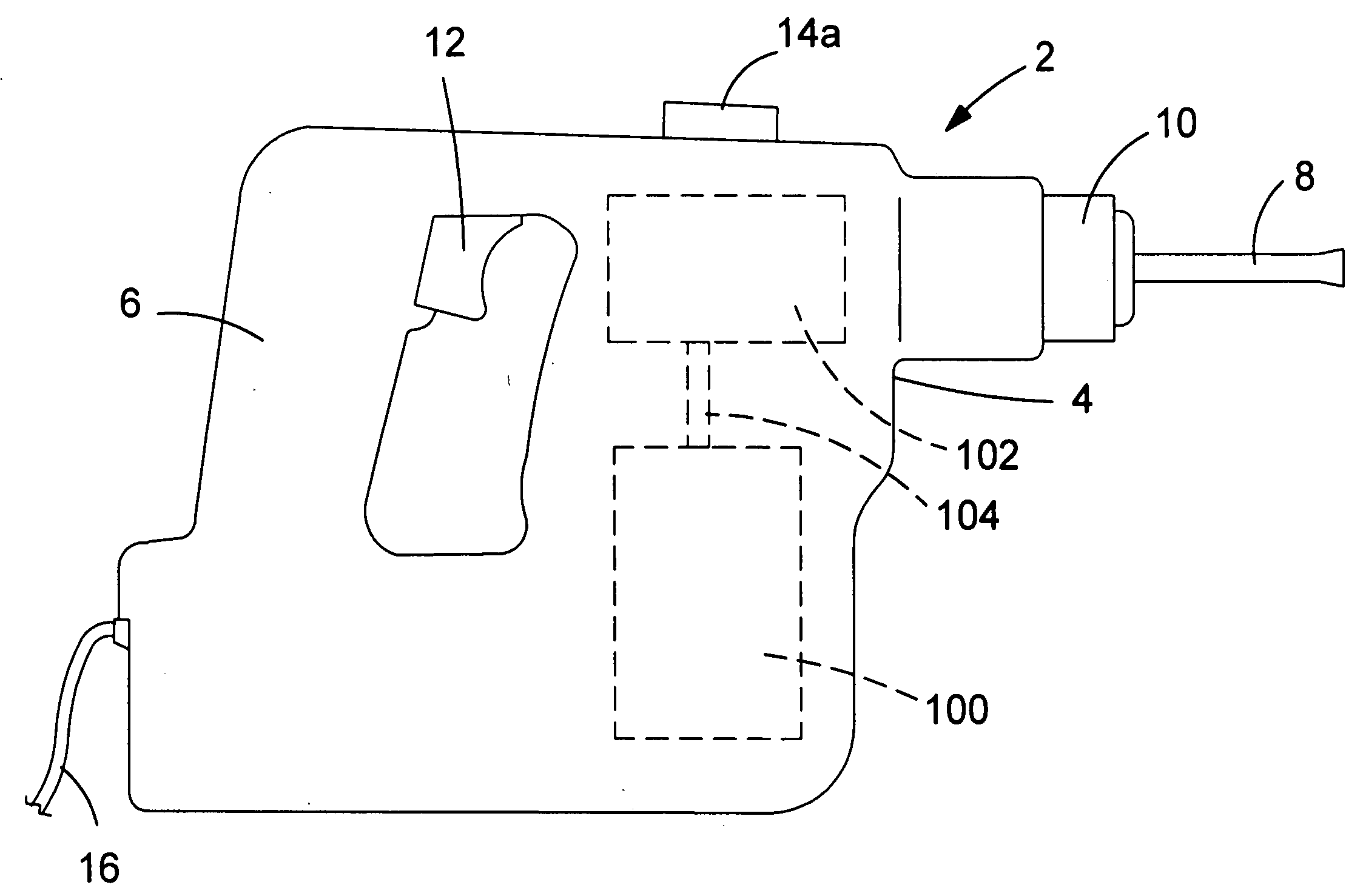
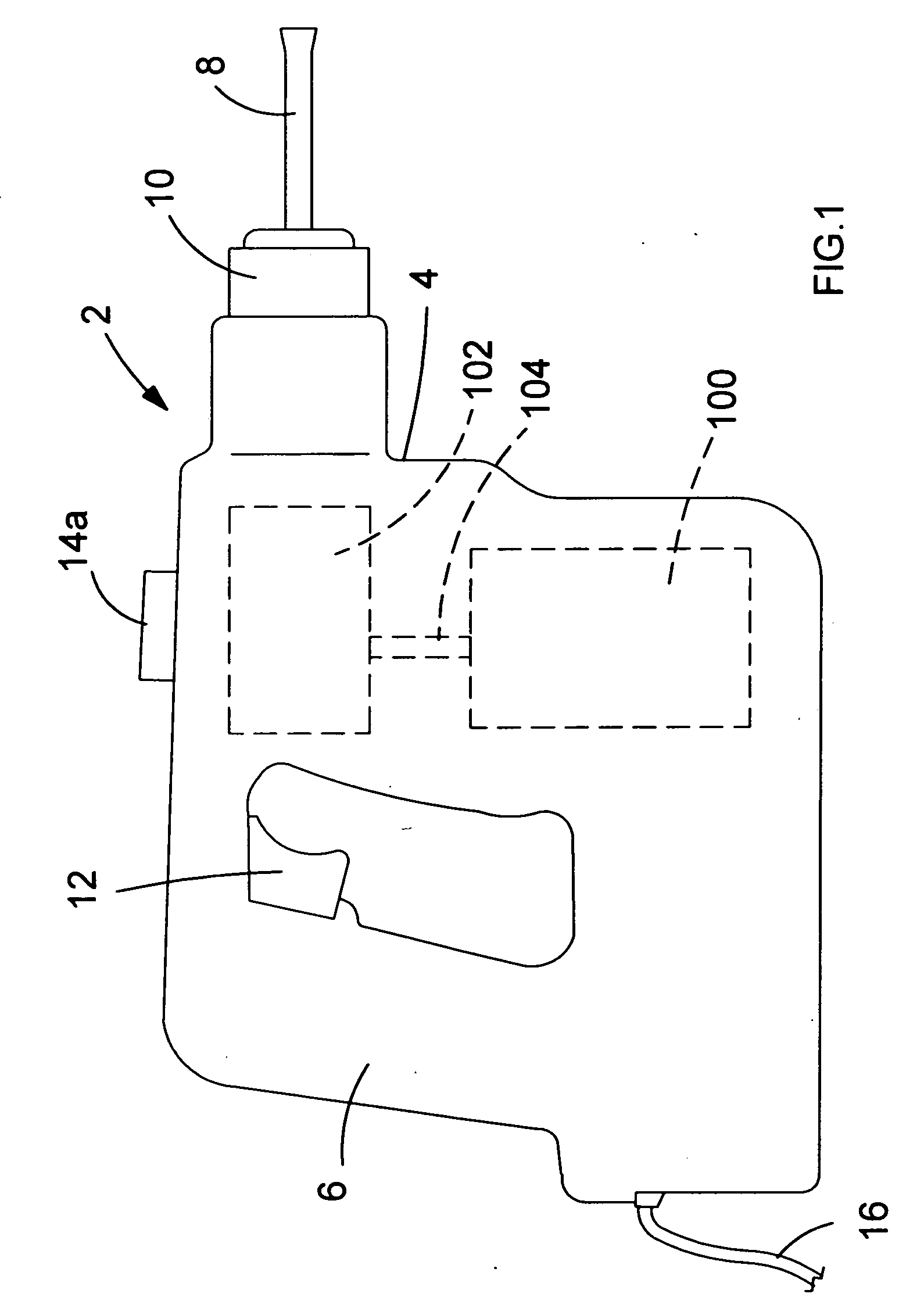
[0028] Referring to FIG. 1, a hammer drill shown generally by 2 comprises a housing 4 having a handle portion 6 for the user to grip. A motor 100 is disposed in the housing 4 which drives a drive mechanism 102 via a rotary output shaft 104, also disposed in the housing 4 and which is capable of driving a bit 8 in a drill mode, in which the bit is rotated, a hammer mode in which impacts are imparted to the bit 8, or a hammer and drill mode, in which both actions are combined. Bit 8 is held in a chuck 10 which is driveably connected to the drive mechanism 104. The operation of the drive mechanism will be familiar to persons skilled in the art and is not relevant to the understanding of the present invention, and will therefore not be described in greater detail herein.

[0029] A trigger 12 is disposed on the handle portion 6 to enable the user to activate the hammer drill 2. A mo...


PUM


Abstract

When the mode change knob of a multi-mode hammer drill is moved to the hammer only position, an electronic sensor sends a signal to a control logic circuit. When the user then depresses the trigger mechanically closing the ON / OFF switch, the control logic circuit applies a voltage either to a holding relay or to the gate of a triac which enables the relay or triac to conduct, thus providing a parallel circuit by-passing the ON / OFF switch. Consequently, when the user releases the trigger and opens the ON / OFF switch, the parallel relay or triac maintains current flow to the motor. It can be seen that in hammer only mode the user can activate the hammer drill by simply tapping the trigger to depress it and does not need to hold down trigger during use of the hammer in operation.

Description

FIELD OF THE INVENTION [0001] The present invention relates to an actuation apparatus for a power tool. In particular, the invention relates to a hammer drill. The invention relates more particularly, but not exclusively to an actuation apparatus for the trigger of a power tool and to a power tool incorporating such an apparatus. BACKGROUND OF THE INVENTION [0002] Hammer drills are power tools that generally have three modes of operation, i.e. a hammer only mode, a drill only mode and a combined hammer and drilling mode. In general, the motor of a hammer drill is operated by the user depressing a spring-loaded trigger, and deactivated by the user releasing the trigger such that it is necessary to hold the trigger down during operation of the tool. [0003] UK patent no. 2314288 describes an electric combination hammer having a drilling mode and a chiselling mode. The hammer comprises a housing with a handle and a trigger disposed on the handle for operating an electric on / off switch. ...

Claims


Application Information

Patent Timeline
Patent Type & Authority Applications(United States)
IPC IPC(8): E02D7/02B25D16/00
CPCB25D16/006B25D2216/0015B25D2216/0023H01H9/06B25D2250/221B25D2250/261B25D2216/0038
Inventor JUNG, ACHIMJAGER, RENEBELL, IAN S.
Owner BLACK & DECKER INC
Learn More