
Adjustable roof rafter clip

a technology of adjustable rafter and rafter clip, which is applied in the direction of portal frames, building roofs, building components, etc., can solve the problems of long-term seasoning of lumber to ensure dimensional stability that is no longer practicable, concomitant increase in construction costs, and dramatic rise in labor charges, so as to achieve easy rotation

Inactive Publication Date: 2006-08-24
INT BUILDING SYST
View PDF10 Cites 26 Cited by
  • Summary
  • Abstract
  • Description
  • Claims
  • Application Information

AI Technical Summary

Benefits of technology

[0019] Finally, it is an aspect of the invention to provide an adjustable roof rafter clip that can be easily pivoted to change the slope range from approximately 10 degrees to at least 30 degrees, thus providing roofs with a pitch ranging from about three to at least six.

Problems solved by technology

Long term seasoning of lumber to ensure dimensional stability is no longer practical in most circumstances.
As the price of wood materials continues to rise and the quality continues to fall, a concomitant increase in construction costs has occurred.
Exacerbating this situation, labor charges have risen dramatically.
Also, law suits over structures that have failed have caused further public pressure to build stronger structures, despite the above-described material problems.
Further, the price of new homes must compete with existing structures even if such dwellings lack the construction improvements provided by the latest techniques.
The downside of such devices, in addition to the cost, is that they add considerable time to the construction process.
If the foundation crew does not provide for such high tolerances, then the bolts will not line up, producing a wall that is out of plumb.
Of course, in order to be able to bend the strap, the gauge of the metal used for such straps must be rather light, thus, at least partially, defeating the purpose of the device.

Method used


Image

  • Adjustable roof rafter clip
  • Adjustable roof rafter clip
  • Adjustable roof rafter clip

Examples


Embodiment Construction

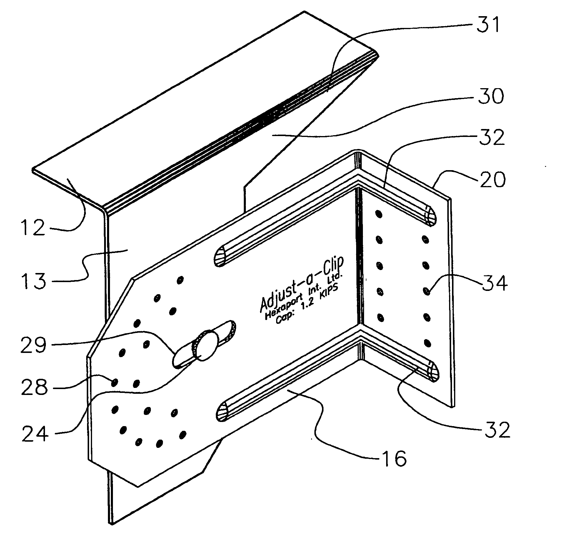
[0028] As shown in FIG. 1a-c, the invention comprises two parts, main body 16 of the clip and the adjusting portion 30. As noted in FIG. 2, adjusting portion 30 is L-shaped, that is, vertical flange 13 and top flange 12. Adjusting portion 30 is preferably made from a single section of galvanized sheet metal that is machine-bent to provide the L-shape.

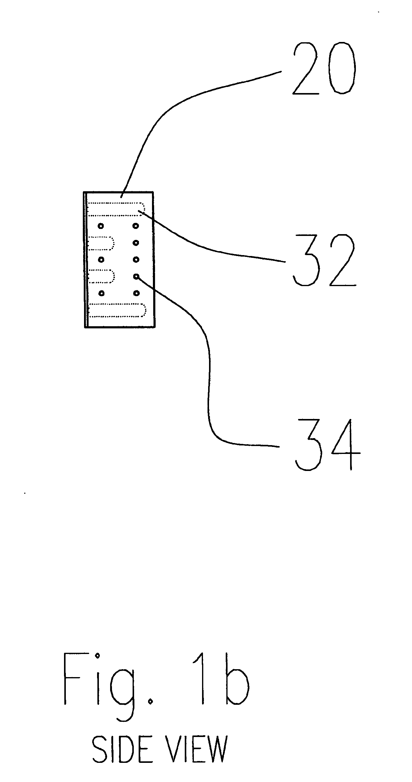
[0029] Similarly, main body 16 of the clip is also an L-shaped single piece of galvanized metal that is stamped from a sheet as noted above. Stiffener detents 32 are pressed into body 16 to increase the rigidity of the structure. Main body 16 is attached to adjusting portion 30 via pivoting pin 24 that is affixed in slot 25 in main body 16. Thus, the angle that is formed when top flange 12 of the adjusting portion 30 is supported against the top of the rafter and the attachment flange 20 of main body 16 is attached to a vertical structure via pre-made holes 34 can be easily adjusted throughout a substantial range.

[0030] The parts are ...


PUM


Abstract

An adjustable roof rafter clip that can be easily pivoted to change the slope range from approximately 10 degrees to at least 30 degrees, thus providing roofs with a pitch ranging from about three to at least six. The invention has two part pivotally attached to one another via a rivet or similar attachment. One part is attached to the roof rafter and the other is attached to a vertical attachment structure. The adjustability of the clip permits the use of heavy gauge galvanized sheet metal which cannot be bent by hand on the job site thus a much stronger clip is provided than those found in the prior art.

Description

FIELD OF THE INVENTION [0001] This invention relates to framing hardware, in particular, an adjustable apparatus for attaching a roof rafter or roof truss to a vertical member of the framing structure such as a top plate of an exterior wall or a ridge board of a roof. BACKGROUND OF THE INVENTION [0002] Construction techniques using standard graded framing lumber has changed considerably over the years. The availability of high quality lumber such as the straight grain fir found in older New England dwellings is no longer present. The definition of kiln-dried lumber has also changed considerably. Long term seasoning of lumber to ensure dimensional stability is no longer practical in most circumstances. Twisted studs, knots, cupping, etc. are all too common. As the price of wood materials continues to rise and the quality continues to fall, a concomitant increase in construction costs has occurred. [0003] Exacerbating this situation, labor charges have risen dramatically. Also, law su...

Claims


Application Information

Patent Timeline
Patent Type & Authority Applications(United States)
IPC IPC(8): E04C3/38
CPCE04B7/045E04B2001/2415E04B2001/2439E04B2001/405E04B2001/389
Inventor ATTALLA, ANTHONY P.BERONEY, MARK
Owner INT BUILDING SYST
Learn More