Integrated phase-shift power control transmitter for use with implantable device and method for use of the same

Active Publication Date: 2006-08-17
ADVNACED BIONICS LLC
View PDF30 Cites 24 Cited by
  • Summary
  • Abstract
  • Description
  • Claims
  • Application Information

AI Technical Summary

Benefits of technology

[0008] The present invention addresses the above and other needs by providing an efficient RF telemetry transmitter system for transmitting power and data to an implant device. The transmitter system uses a phase delay (e.g., time delay or phase shift) technique to control the power level of the signal being transmitted to the implant device. Such a technique advantageously eliminates the need of an additional voltage regulator (e.g., a switching voltage regulator) and its associated discrete components to control the voltage of the transmitted RF signal. In addition, this technique enables the transmitter to accurately control the magnitude of the RF signal to assure optimum power transfer to the implant device. Thus, the amount of power provided to the implant device can be set to a level required by the implant device. That is, an oversupply (which may result in wasted power) and an undersupply (which may result in improper implant device operation) of power to the implant device is avoided.

Problems solved by technology

Cochlear implant technology is well known and has been successfully used to enable individuals to hear, whereas other hearing assist devices, such as hearing aids and head phone amplifiers, have failed.
Traditional power conversion and transfer techniques, although are able to provide power to the implanted device, do not completely meet the stringent criteria.
As a result, the external unit of the cochlear implant systems may require bulky housings, large power requirements, and frequent replacement or charging of batteries.
A drawback with this technique is that the voltage regulator requires additional circuitry such as control circuitry and discrete components such as inductors and capacitors to operate.
These additional components add costs, consume additional power, and occupy extra space.
One drawback of using PWM to control the transmitter power output is that both even and odd higher order harmonics may be imposed on the carrier signal.
The production of both even and odd harmonics places a substantial burden on filtering circuitry because if the higher order harmonics currents are not suppressed, these harmonic currents can decrease the power efficiency of the transmitter circuitry.
The production of undesirable second harmonics increases the steepness of the suppression filter circuits, which generally increases the order of the filter and the inherent losses in such filters.
Moreover, another drawback is that the control of the duty cycle may be difficult as it approaches zero, thus potentially preventing accurate control of power across the entire available range of power that can be transmitted on the carrier signal.
Furthermore, as cochlear implant devices advance, other components such as digital processing circuitry may require increased levels of power and space.

Method used


Image

  • Integrated phase-shift power control transmitter for use with implantable device and method for use of the same
  • Integrated phase-shift power control transmitter for use with implantable device and method for use of the same
  • Integrated phase-shift power control transmitter for use with implantable device and method for use of the same

Examples


Embodiment Construction

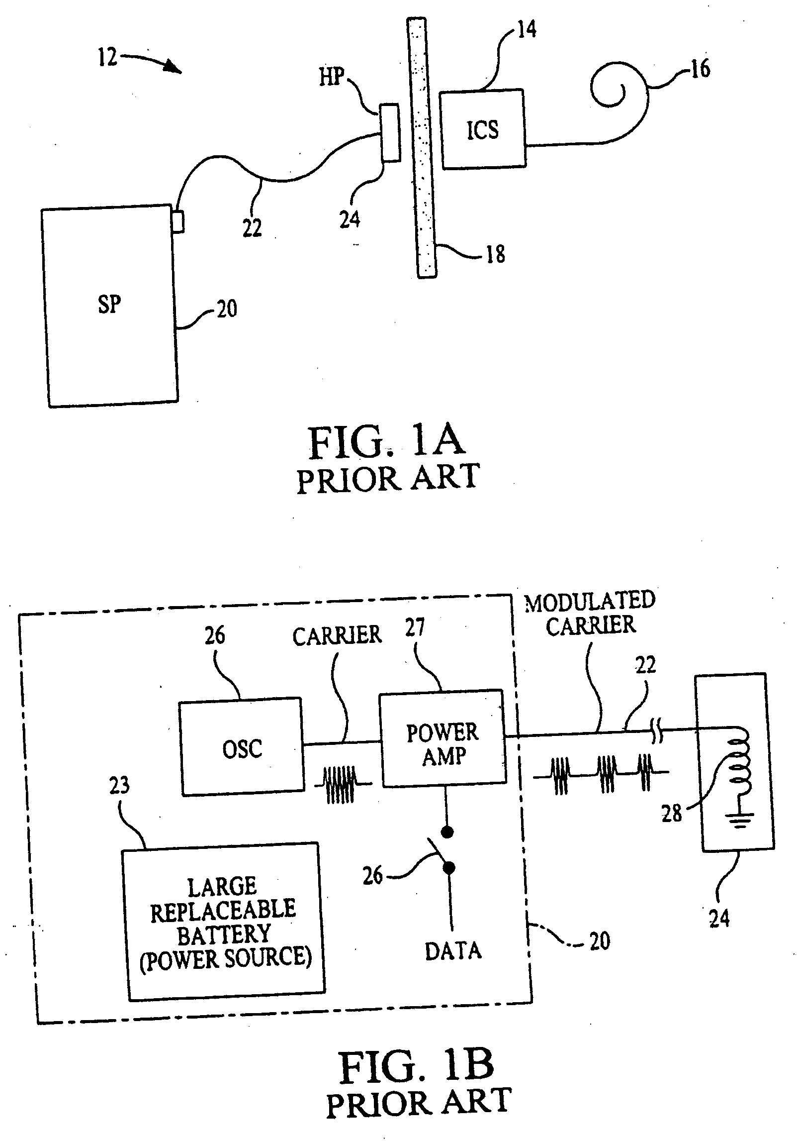
[0031]FIG. 1A shows a representative block diagram of an ICS system 12 of the type commonly found in the prior art. A thorough description of a cochlear stimulation system of the type shown in FIG. 1A may be found, for example, in U.S. Pat. No. 5,776,172, which is incorporated herein by reference in its entirety. As seen in FIG. 1A, the ICS system 12 includes an implanted portion, including an ICS 14 and an electrode array 16, and an external portion, comprising a speech processor (SP) 20 connected to a headpiece 24 via a long cable 22. The implanted portion is separated from the external portion by a barrier such as, for example, a layer of skin 18.

[0032] In operation, the prior art ICS system 12 of FIG. 1A transmits power and data through the skin barrier 18 to the implantable portion using a technique as illustrated generally in the functional block diagram of FIG. 1B. The ICS system 12 uses the received data and power to provide stimulation pulses to select electrode pairs loca...


PUM


Abstract

Systems and methods for efficiently transmitting power using a high frequency (e.g., RF) telemetry transmitter are provided. The telemetry transmitter may include a fixed clock source (which may provide a fixed clock signal), telemetry phase shift circuitry (which may include switching circuitry and phase shifting circuitry), and a push-pull network. The telemetry phase shift circuitry generates a phase shifted clock signal that is phase shifted with respect to the fixed clock signal. The fixed and phase shifted clock signals may drive the switching circuitry to produce a high frequency signal that is passed through the push-pull network. The power or magnitude of the high frequency signal is based on the phase delay between the fixed clock signal and the phase shifted clock signal.

Description

BACKGROUND OF THE INVENTION [0001] The present invention relates to methods and systems for controlling the power level of high frequency signals, and more particularly to RF telemetry transmitters for efficiently communicating with and powering an implanted stimulator device (e.g., an implanted cochlear stimulator (ICS)). [0002] Cochlear implant technology is well known and has been successfully used to enable individuals to hear, whereas other hearing assist devices, such as hearing aids and head phone amplifiers, have failed. Generally, cochlear implant systems include an external unit and an implanted device. The external unit usually includes a power source (e.g., a battery), where the implanted device may not. The implanted device may receive power from the external unit by way of an inductive or radio frequency (RF) link. To transfer power from the external unit to the implanted device, the external unit and implanted device may each include a coil. Although these coils are n...

Claims


Application Information

Patent Timeline
IPC IPC(8): A61N1/08A61N1/40A61N1/10
CPCA61N1/36032A61N1/3727A61N1/36038
Inventor GRIFFITH, GLEN A.
Owner ADVNACED BIONICS LLC
Why Eureka
Try Eureka