
Scanning system with stereo camera set

a scanning system and stereo camera technology, applied in the field of surface inspection systems, can solve the problems of reducing system life, wide range of problems, and insufficient precision and accuracy for quality control of parts requiring highly precise tolerances

Inactive Publication Date: 2006-08-17
DIMENSIONAL TECH INT
View PDF9 Cites 34 Cited by
  • Summary
  • Abstract
  • Description
  • Claims
  • Application Information

AI Technical Summary

Problems solved by technology

Even the human eye with its remarkable ability to capture huge amounts of optical information cannot make measurements with precision and accuracy sufficient for quality control of parts requiring highly precise tolerances.
Failure to achieve proper measurements can result in a wide range of problems.
For example, failure to maintain dimensional tolerances for parts in an automobile engine may result in problems ranging from decreased system life to increase probability of failure under out of the ordinary conditions.
Even where later system testing at a manufacturing facility can detect problems resulting from failure to meet dimensional tolerances, unacceptably high rejection rates on account of defective systems can result.
Moreover, even when human eye is capable of performing a required inspection, such factors as fatigue, lighting, distraction and so forth make human inspection unreliable.
With such systems, however, the resolution of the optical inspection apparatus is far below that of the human eye.
There are many relatively low priced color and black and white array CCD detectors available for video imaging, but they produce low quality images, as alluded to above.
More particularly, CCD detectors and other video imaging devices suffer from a relatively low pixel count.
However, these arrays are presently very expensive.
Moreover, these very large arrays tend to have defects such as inoperative pixels, inoperative clusters of pixels, or inoperative lines of pixels.
When very high quality images are required this type of electronic imaging system is not only very expensive.
Such systems may not even be capable of performing a high-quality, high precision measurement.
Such a system, while suitable for making high quality digital images for commercial photography, is inappropriate for use in making high precision measurements.
More particularly, mechanical irregularities in the scanning assembly make the generation of highly precise image information impossible, thus making the image data captured by such systems on suitable for the purpose of confirming dimensional tolerances in a precision manufacturing environment.

Method used


Image

  • Scanning system with stereo camera set
  • Scanning system with stereo camera set
  • Scanning system with stereo camera set

Examples


Embodiment Construction

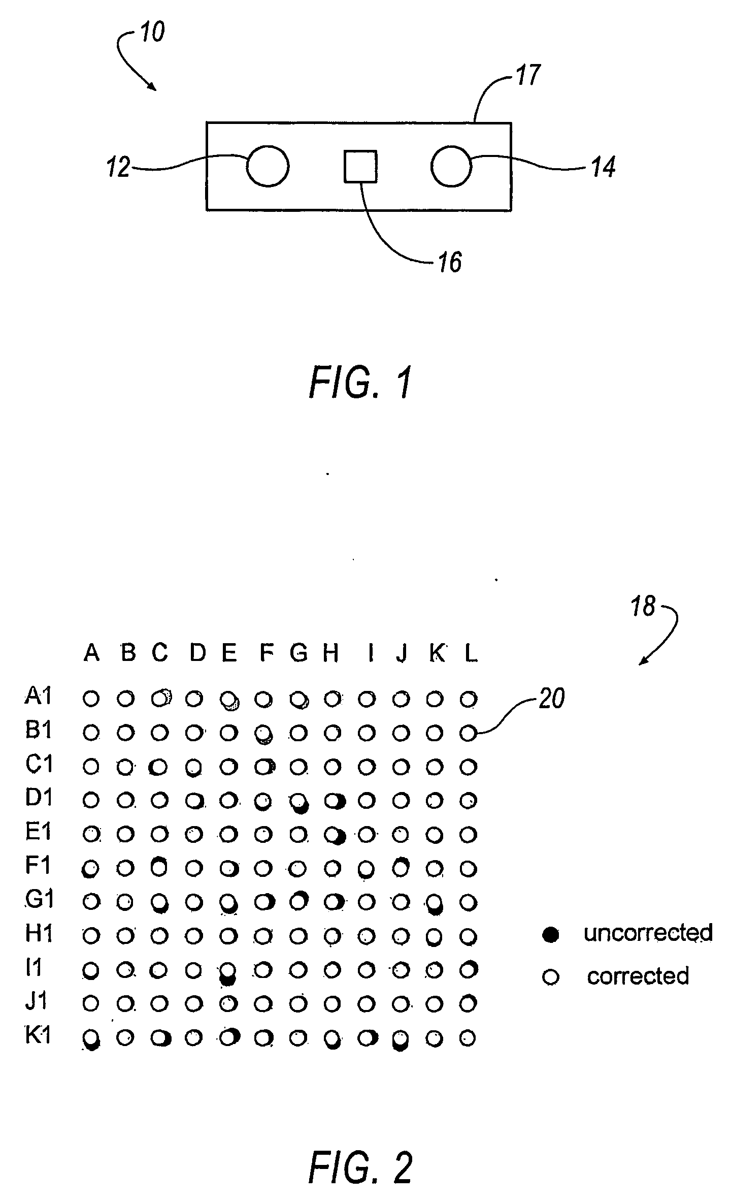
[0027] Referring now to FIG. 1, a scanning system according to the invention comprises a stereo camera set, shown generally at 10, that includes a pair of optical devices, such as cameras 12, 14 and an illumination device 16, such as a projector, or the like. The cameras 12, 14 and the projector 16 of the stereo camera set 10 may be mounted or affixed to a frame 17. The cameras 12, 14 are preferably cameras having a matrix array of charge-coupled devices (CCD) of a type well-known in the art. In addition, the invention is not limited by the type of camera, and the invention can be practiced with any desirable type of camera, such as a camera using Complementary Metal Oxide Semiconductor (CMOS) technology, or the like.

[0028] An ideal camera using a CCD matrix array, for example, has a distortion free optical system (e.g., a lens) and a perfectly arranged CCD matrix array that would “see” or detect a dot matrix reference system 18 of matrix dots 20, as shown by the white dots in FIG....


PUM

PropertyMeasurementUnit
distanceaaaaaaaaaa
lengthaaaaaaaaaa
lengthaaaaaaaaaa

Abstract

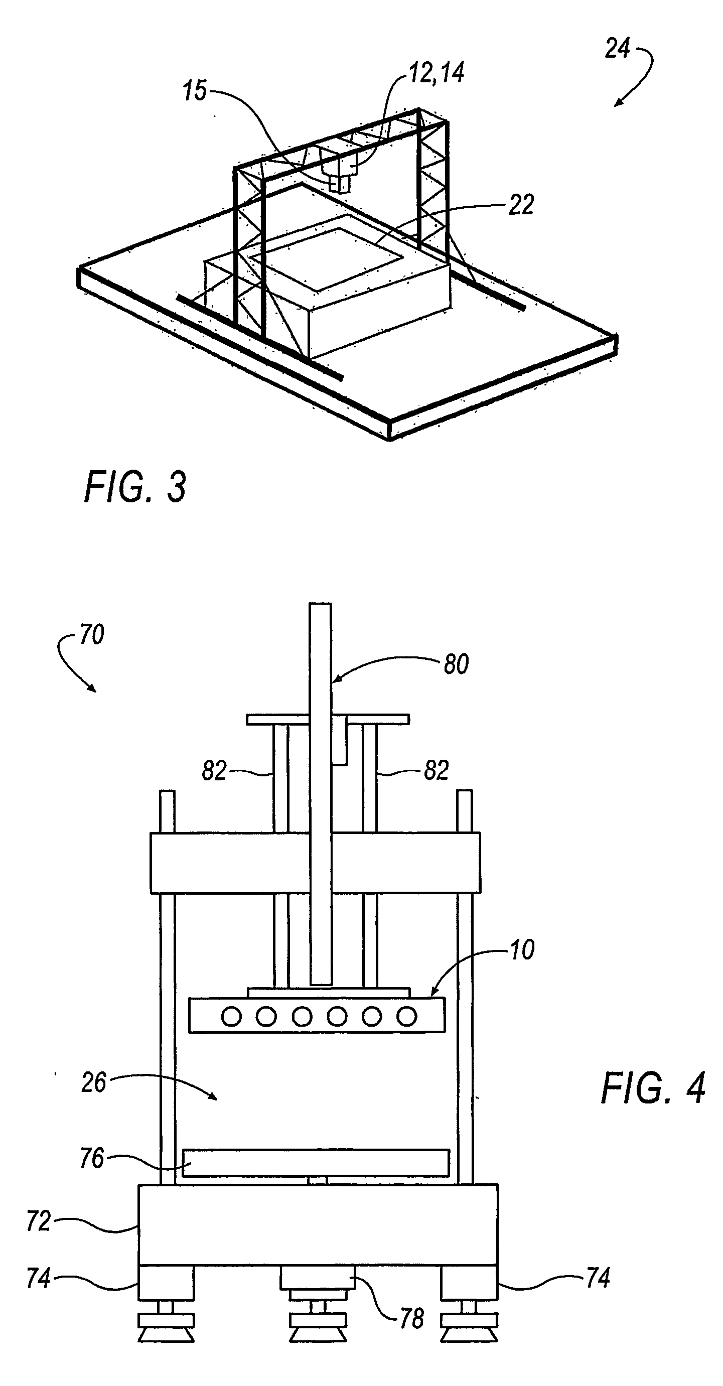
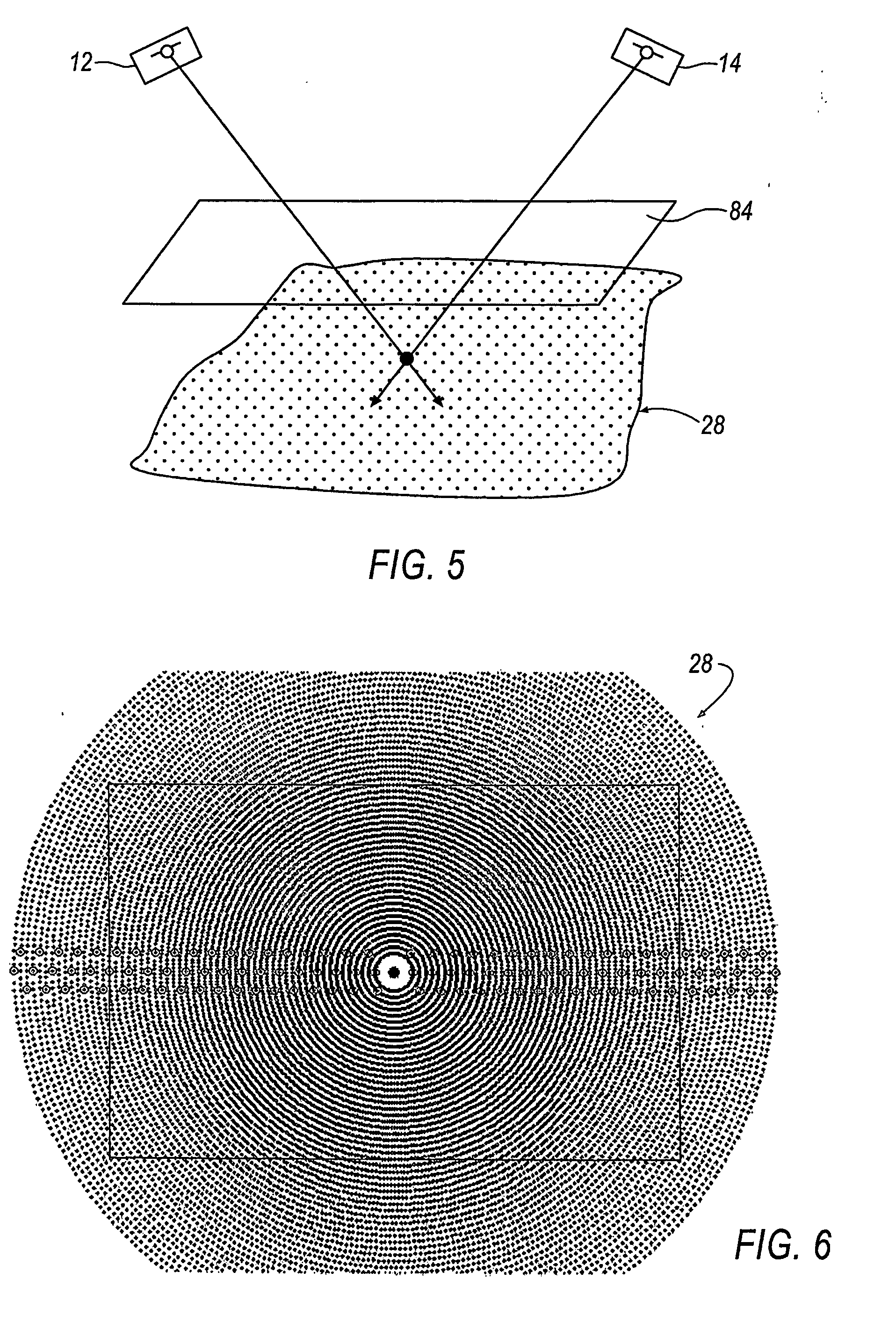
A scanning system includes one or more stereo camera sets (10) for detecting qualitative and quantitative anomalies of an object (40). Each stereo camera set (10) includes two cameras (12, 14) and a projector (16). Each camera (12, 14) is calibrated to correct any distortion due to misalignment of the CCD matrix array (18) and deficiencies of the optical system. The projector (16) projects an absolute encoded pattern (32, 34, 36) onto the object (40) to be measured and is capable of varying the intensity of the emitted electromagnetic energy in the infrared, visible and ultraviolet spectrums. A plurality of camera sets (10) can be combined in a scanning system matrix (42, 44) capable of detecting anomalies of the object (40) in a three-dimensional room (26). The three-dimensional room (26) can be of any desirable size, depending on the number of stereo camera sets (10). The data from the cameras (12, 14) is pre-processed by gate arrays (62) before being transmitted via digital signal processors (66) to a computer interface (64) for display of the measurement. As a result, the amount of data transferred is streamlined, thereby reducing operating time and enabling the scanning system to very accurately detect anomalies of the object (40) in a very short period of time.

Description

BACKGROUND OF THE INVENTION [0001] 1. Field of the Invention [0002] This invention relates in general to surface inspection systems, and in particular, to a high speed scanning system for detecting anomalies of an object with high precision by using one or more stereo camera sets. [0003] 2. Description of the Related Art [0004] Even the human eye with its remarkable ability to capture huge amounts of optical information cannot make measurements with precision and accuracy sufficient for quality control of parts requiring highly precise tolerances. Failure to achieve proper measurements can result in a wide range of problems. For example, failure to maintain dimensional tolerances for parts in an automobile engine may result in problems ranging from decreased system life to increase probability of failure under out of the ordinary conditions. Even where later system testing at a manufacturing facility can detect problems resulting from failure to meet dimensional tolerances, unaccept...

Claims


Application Information

Patent Timeline
Patent Type & Authority Applications(United States)
IPC IPC(8): G06K9/00G01B11/25G01N21/88
CPCG01B11/2545G01N21/8806G06T7/0006G06T7/0075G06T2207/30164G06T7/593G01N21/88
Inventor GERLACH, DIETERKELLNER, HELMUT
Owner DIMENSIONAL TECH INT
Learn More