
Microphone assembly

a microphone and assembly technology, applied in the direction of magnets, magnets, propulsion systems, etc., can solve the problems of increasing the weight and complexity of the magnetic system, increasing the force on the coil, and nonlinearity in the response of the coil

Inactive Publication Date: 2006-08-17
TRANDAFIR ROLAND PIERRE
View PDF2 Cites 20 Cited by
  • Summary
  • Abstract
  • Description
  • Claims
  • Application Information

AI Technical Summary

Benefits of technology

The present invention is about an electromagnetic transducer that includes a magnet assembly and a conductive drive coil. The magnet assembly has outer pole faces and a magnetic field that emanates radially outward. The drive coil is a flat ring coil located in the magnetic field. The drive coil moves along an excursion path and is mounted close to the magnet assembly, allowing for relative axial motion between them. The invention can be used as a motor or a generator, and different shapes of the magnet assembly can be used. The invention also describes speaker and microphone devices formed using the electromagnetic transducer. The technical effects of the invention include improved performance and efficiency of electromagnetic transducers and flexibility in magnet assembly shape.

Problems solved by technology

These steps increase the weight and complexity of the magnetic system and further cause an increase in the force on the coil, which leads to nonlinearity in the coil's response to the magnetic field as the coil oscillates during its excursion.
In general, such systems are inefficient because they require many windings in order for their drive cylinder to effectively interact with the increased magnetic field size.
In addition, they tend to overheat and / or require cooling, and they tend to develop various signal distortions during use.
In sum, the above problems cause the '260 devices to be inefficient, heavy, and expensive to manufacture.
In addition, extensive periods of zero or reverse force on the coil persist at pole reversal.
The '886 device is still relatively heavy and still requires a tall, cylindrical drive coil to interact with the magnetic field at close range.
The '784 device suffers, however, in that the diaphragm is limited in the distance it can travel during use, since it will rapidly hit the magnet face if the input signal is of sufficient strength.
This can affect signal purity and can be a source of signal distortion.
As in the '784 device, though, the '805 device is limited in the distance the diaphragm can travel before it hits one of the cylinder magnets.
This design also suffers from the relatively minor amount of interaction between the planar coil windings and the radially emanating magnetic field.

Method used


Image

  • Microphone assembly
  • Microphone assembly
  • Microphone assembly

Examples


Embodiment Construction

[0048] This invention relates to transducer motor and / or generator assemblies and particularly to a returnless transducer assembly construction. The invention is for use in numerous contexts, including sonic devices, relays, switches, oscillators, and other energy-transforming devices, in the extremely low frequency through ultrasonic and radio frequency spectra, as sensors or signal emitters.

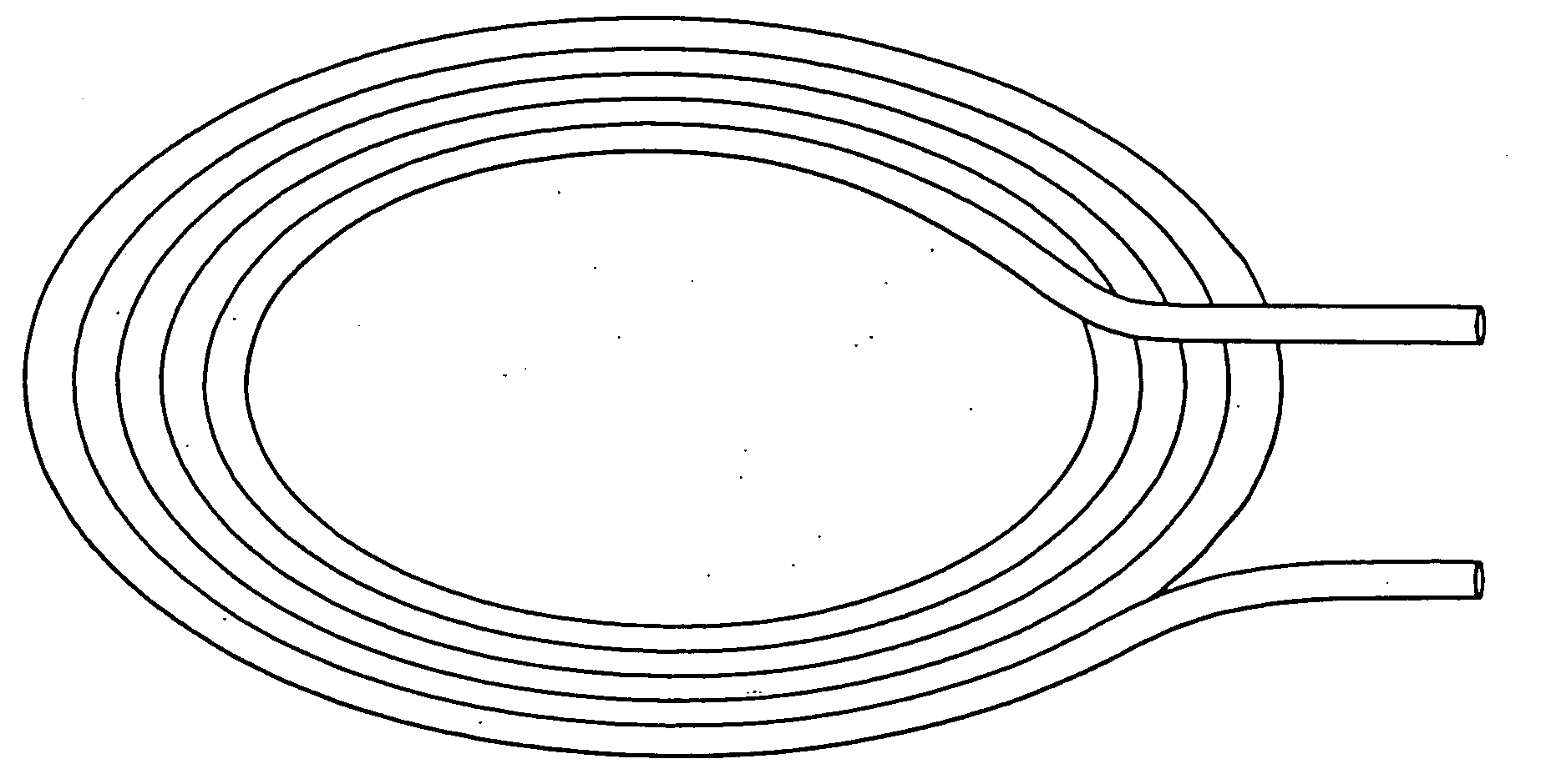
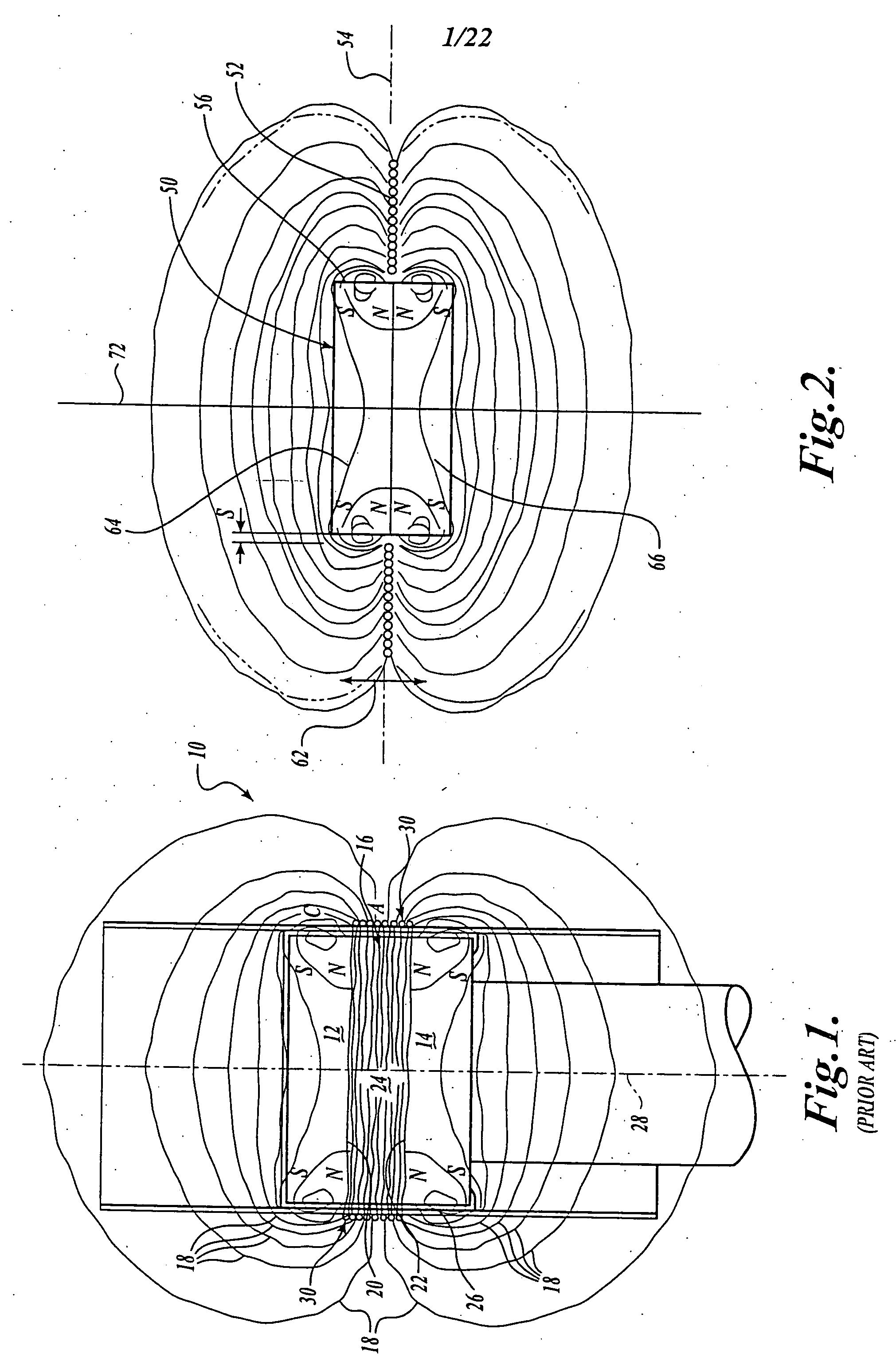
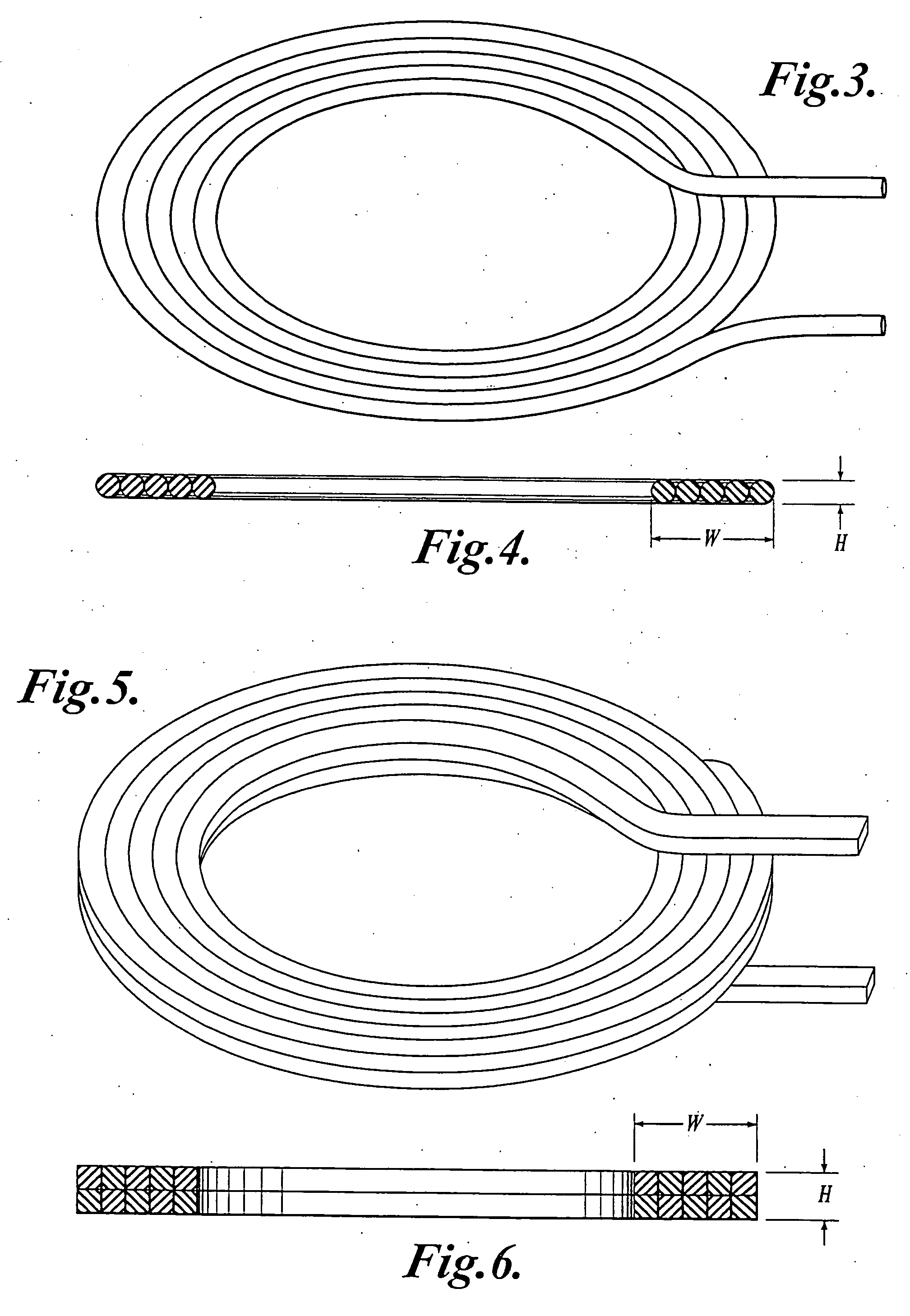
[0049] In general and referring now to FIG. 2, a permanent magnet assembly 50 is provided for reciprocating a current-carrying conductor 52 formed in a horizontal plane 54. The magnet assembly provides a magnetic field that extends outward of and transverse to a vertical, or axial, magnet direction. (The directions provided in this description are in reference only to the drawings provided. During use, the “vertical” direction may in fact be horizontal or at an angle, while the “horizontal” direction may be vertical or at an angle.) Conductor 52 is spaced from the outer surface 56 of assembly ...


PUM

PropertyMeasurementUnit
axial magnetizationaaaaaaaaaa
magnetic fieldaaaaaaaaaa
outer sizeaaaaaaaaaa

Abstract

An electromagnetic transducer is described including a magnet assembly (50) and a conductive drive coil (52). The magnet assembly provides an emanating magnetic field within which the drive coil is located. The drive coil is a flat ring coil having a width that is equal to or greater than its height. As assembled, the drive coil is mounted in close proximity to the magnet assembly such that relative axial motion may occur between them during use. In one embodiment, the magnet assembly includes two permanent disc magnets (64), (66) having axial magnetizations and being oriented with like poles facing one another to produce a radially emanating magnetic field. In another embodiment, the magnet assembly includes a pair of axially magnetized permanent ring magnets (64), (66) also oriented with like poles facing one another.

Description

FIELD OF THE INVENTION [0001] The present invention relates to electricity and magnetically operated switches, magnets, and electromagnets; and more particularly, to magnetomechanical motive devices with relatively movable coil and permanent magnet assemblies. BACKGROUND OF THE INVENTION [0002] Various types of transducer assemblies are known. One type, shown in U.S. Pat. No. 5,142,260 to William N. House, is illustrated in FIG. 1. This assembly includes a magnetic circuit structure 10 with two aligned magnetic discs 12, 14, which are axially polarized and oriented so their resultant flux fields oppose one another. A spacer 16 of either ferrous or nonferrous material is sandwiched between the magnets 12, 14 to help control the magnetic field characteristics. As a result of the opposing axial alignment, magnetic flux lines 18 emanate from the magnetic poles 20, 22 that face each other and are focused and directed radially outward from the region 24 between the magnets 12, 14. [0003] ...

Claims


Application Information

Patent Timeline
Patent Type & Authority Applications(United States)
IPC IPC(8): H04R1/00H04R9/06H04R11/02H01F7/04H01F7/06H02K33/18H02K35/04H02K41/035H04R1/06H04R9/02H04R9/04
CPCH01F7/066H02K35/04H02K41/0356H04R2499/13H04R9/025H04R9/046H04R9/06H04R1/06H02K33/18H04R9/00H04R11/00
Inventor TRANDAFIR, ROLAND PIERRE
Owner TRANDAFIR ROLAND PIERRE
Learn More