
Reflective display device

a display device and display screen technology, applied in the field of reflection display devices, can solve the problems of difficult to define the corner cubes with high plane accuracy, the corner cubes actually have some errors in their “normal angle” or their degree of planarity, and achieve the effect of improving the display quality

Active Publication Date: 2006-08-17
SHARP KK
View PDF5 Cites 19 Cited by
  • Summary
  • Abstract
  • Description
  • Claims
  • Application Information

AI Technical Summary

Benefits of technology

[0025] In order to overcome the problems described above, an object of the present invention is to eliminate such dark-state leakage or grayscale inversion and get the display quality improved by using a reflective display device including a retroreflective layer with an MCCA shape.
[0035] According to various preferred embodiments of the present invention described above, the dark-state leakage phenomenon can be reduced significantly in a reflective display device including a retroreflective layer and the display contrast ratio thereof can be increased. In addition, the grayscale inversion can also be reduced and excellent display quality, including good visibility, is realized. Furthermore, the dark-state leakage and grayscale inversion can be minimized no matter from which direction the viewer is watching the screen of the display device.

Problems solved by technology

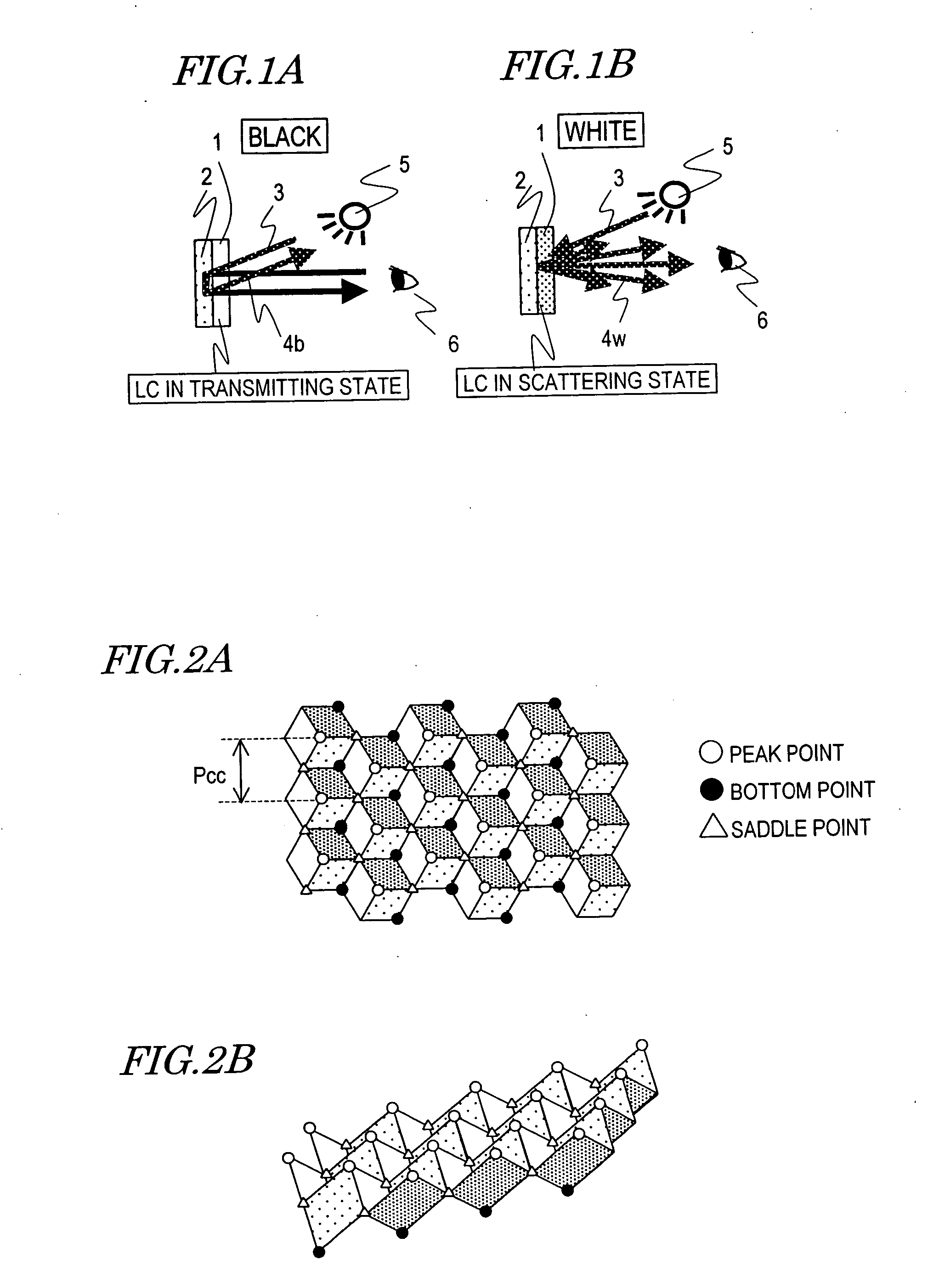
That is why in a reflective display device using such an MCCA, even if the viewer faces its screen squarely, part of the external light to be used for display purposes in a black display mode will enter his or her eyes, thus causing the dark-state leakage or grayscale inversion mentioned above.
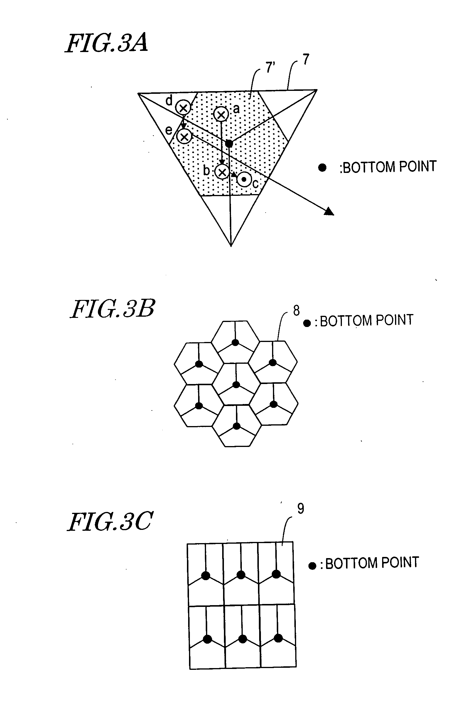
Furthermore, no matter what planar pattern each of the corner cubes of an MCCA has, it is extremely difficult to define the corner cubes with high plane accuracy, particularly when the corner cubes are arranged at a very small pitch in the MCCA.
Thus, each corner cube will actually have some errors in its “normal angle” or its degree of planarity.
On the other hand, the error of the planarity refers to partial or entire warp of some plane of a corner cube and to rounding of the peak or bottom point of a corner cube.
As a result, even if the viewer is facing the screen squarely, dark-state leakage or grayscale inversion may still happen.
Consequently, it is difficult to eliminate such dark-state leakage or grayscale inversion and get excellent display quality realized by using a conventional reflective display device with an MCCA.

Method used


Image

  • Reflective display device
  • Reflective display device
  • Reflective display device

Examples


embodiment1

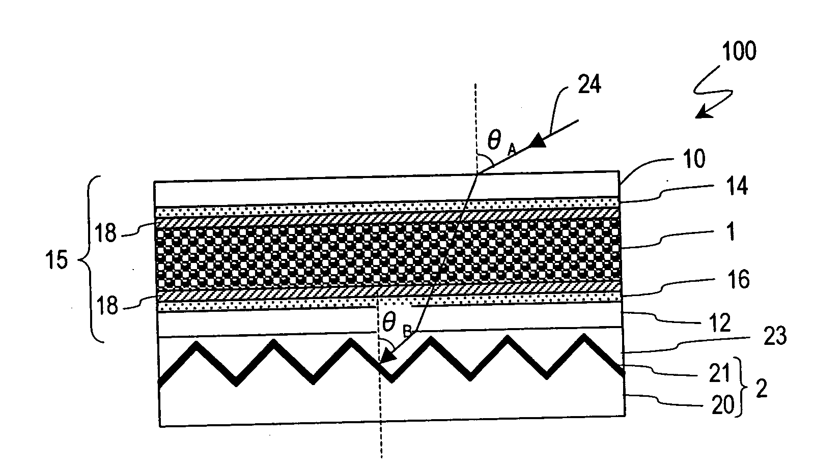
[0086] Hereinafter, a display device according to a first preferred embodiment of the present invention will be described with reference to the accompanying drawings. The display device of this preferred embodiment is a reflective display device that has an MCCA attached structure and in which the gap between the rear substrate of the display panel and the retroreflective layer with the MCCA shape is filled with a gas having a refractive index of about 1.00.

[0087]FIG. 10A is a schematic cross-sectional view illustrating a configuration for the reflective display device of this preferred embodiment. As can be seen from FIG. 10A, the display device of this preferred embodiment has substantially the same configuration as the display device 100 shown in FIG. 4. In FIG. 10A, any component having almost the same function as the counterpart shown in FIG. 4 will be identified by the same reference numeral for the sake of simplicity and the description thereof will be omitted herein. FIG. 1...

embodiment 2

[0113] Hereinafter, a display device according to a second preferred embodiment of the present invention will be described with reference to the accompanying drawings. The display device of this preferred embodiment is a reflective display device having an MCCA attached structure.

[0114]FIG. 15 is a schematic cross-sectional view illustrating a configuration for a reflective display device according to this preferred embodiment. The reflective display device of this preferred embodiment has almost the same configuration as the counterpart of the first preferred embodiment that has already been described with reference to FIG. 10A except that the gap between the rear substrate 12 of the display panel and the retroreflective layer 2 is filled with a liquid or solid 83 having a refractive index of 1.06 or more. In this preferred embodiment, a resin 83 with a refractive index of 1.5 is used as the liquid or solid. Although not shown, the retroreflective layer 2 of this preferred embodim...

embodiment 3

[0126] Hereinafter, a display device according to a third preferred embodiment of the present invention will be described with reference to the accompanying drawings. The display device of this preferred embodiment is a reflective display device having an MCCA embedded structure.

[0127]FIG. 17 is a schematic cross-sectional view illustrating a configuration for a reflective display device according to this preferred embodiment. The display device of this preferred embodiment includes a front substrate 110 with color filters 120, a transparent electrode 114 and an alignment film 118, a rear substrate 112, which is arranged so as to face the front substrate 110, and a liquid crystal layer 101 interposed between these substrates 110 and 112. The rear substrate 112 includes a plurality of TFTs 124 functioning as switching elements, an insulating layer 126 with an MCCA shape provided on the TFTs 124, a plurality of reflective electrodes 122 and an alignment layer 118. The reflective elec...


PUM


Abstract

A reflective display device includes a retroreflective layer including a plurality of unit structures that are arranged two-dimensionally on a virtual plane and a modulating layer, which is arranged closer to a viewer than the retroreflective layer is and which is switchable between a first state and a second state that have mutually different optical properties. The reflective display device conducts a display operation by using light that has been reflected back from the retroreflective layer. Each unit structure of the retroreflective layer has a recess defined by three planes that are opposed substantially perpendicularly to each other. The unit structures are arranged so as to face substantially the same direction. An azimuthal direction, which is defined by projecting a normal to one of the three planes onto the virtual plane, and another azimuthal direction, which is defined by projecting a screen downward direction onto the virtual plane, form an angle of less than 30 degrees.

Description

BACKGROUND OF THE INVENTION [0001] 1. Field of the Invention [0002] The present invention relates to a reflective display device including a retroreflective layer. [0003] 2. Description of the Related Art [0004] A reflective liquid crystal display device for conducting a display operation by utilizing surrounding light as its light source has been known in the art. Unlike a transmissive liquid crystal display device, the reflective liquid crystal display device needs no backlight, thus saving the power for light source and allowing the user to carry a smaller battery. Also, the space to be left for the backlight in a transmissive device or the weight of the device itself can be saved. For these reasons, the reflective liquid crystal display device is effectively applicable to various types of electronic devices that should be as lightweight and as thin as possible. [0005] A technique of combining a scattering type liquid crystal display mode and a retroreflector is one of known meas...

Claims


Application Information

Patent Timeline
IPC IPC(8): G09G3/34
CPCG02B5/124G02F1/133555G02F1/1335G09F9/30
Inventor SATOH, EIJI
Owner SHARP KK
Learn More