
Non-leaded integrated circuit package system

a technology of integrated circuits and packages, applied in the direction of electrical equipment, semiconductor devices, semiconductor/solid-state device details, etc., can solve the problems of low market penetration of pad-up qfn packages, inability to mount packages vertically or be required to use external sockets, and the cost of diamond saw blades continues to increas

Active Publication Date: 2006-08-17
STATS CHIPPAC LTD
View PDF25 Cites 42 Cited by
  • Summary
  • Abstract
  • Description
  • Claims
  • Application Information

AI Technical Summary

Problems solved by technology

The low market penetration stems from QFN architectures that have hanging leads on the outer leads portion resulting in the package sides having interconnectivity rather than at the conventional surface mount plane (the package bottom).
Most surface mount technology (SMT) end-users found it impractical to mount packages vertically or be required to use external sockets to a printed circuit board (PCB).
Another cause for the low market penetration for the pad-up QFN package is that most QFN manufacturing for the SMT interface used a saw singulation method.
The cost of diamond saw blades continues to increase resulting in an overall cost increase of the QFN package technology.
Wire bonding processes become critical and difficult to control due thermosonic energy transmission into the hanging leads, which result in leads that bounce during the wire bonding.
It is not viable to have differential height lead structures unsupported during the wire bonding process as taping hinders the use of a protruded islands heater block design.
These complications resulted in reduced development for differential height lead structures design, except a few applications in the memory module packaging industry.
While punch singulation solved some of the problems, it also created some other critical problems.
The leads being raised on the external portion of the interconnecting pad increases the risk for lead deflection during punch singulation resulting in defects such as distorted leads, metal burr, wire bond stitch cracking and metal bridging.
Lead deflection also results in degraded package integrity prompting mold compound and metal lead delamination.
Delamination causes moisture penetration, package cracks, and moisture resistance test (MRT) failure.
Solutions to these problems have been long sought but prior developments have not taught or suggested any solutions and, thus, solutions to these problems have long eluded those skilled in the art.

Method used


Image

  • Non-leaded integrated circuit package system
  • Non-leaded integrated circuit package system
  • Non-leaded integrated circuit package system

Examples


Embodiment Construction

[0025] In the following description, numerous specific details are given to provide a thorough understanding of the invention. However, it will be apparent that the invention may be practiced without these specific details. In order to avoid obscuring the present invention, some well-known system configurations, and process steps are not disclosed in detail. Likewise, the drawings showing embodiments of the apparatus are semi-diagrammatic and not to scale and, particularly, some of the dimensions are for the clarity of presentation and are shown greatly exaggerated in the figures. Generally, the device can be operated in any orientation. Also, where multiple embodiments are disclosed and described having some features in common, for clarity and ease of illustration, description, and comprehension thereof, similar and like features one to another will ordinarily be described with like reference numerals.

[0026] The term “horizontal” as used herein is defined as a plane parallel to th...


PUM


Abstract

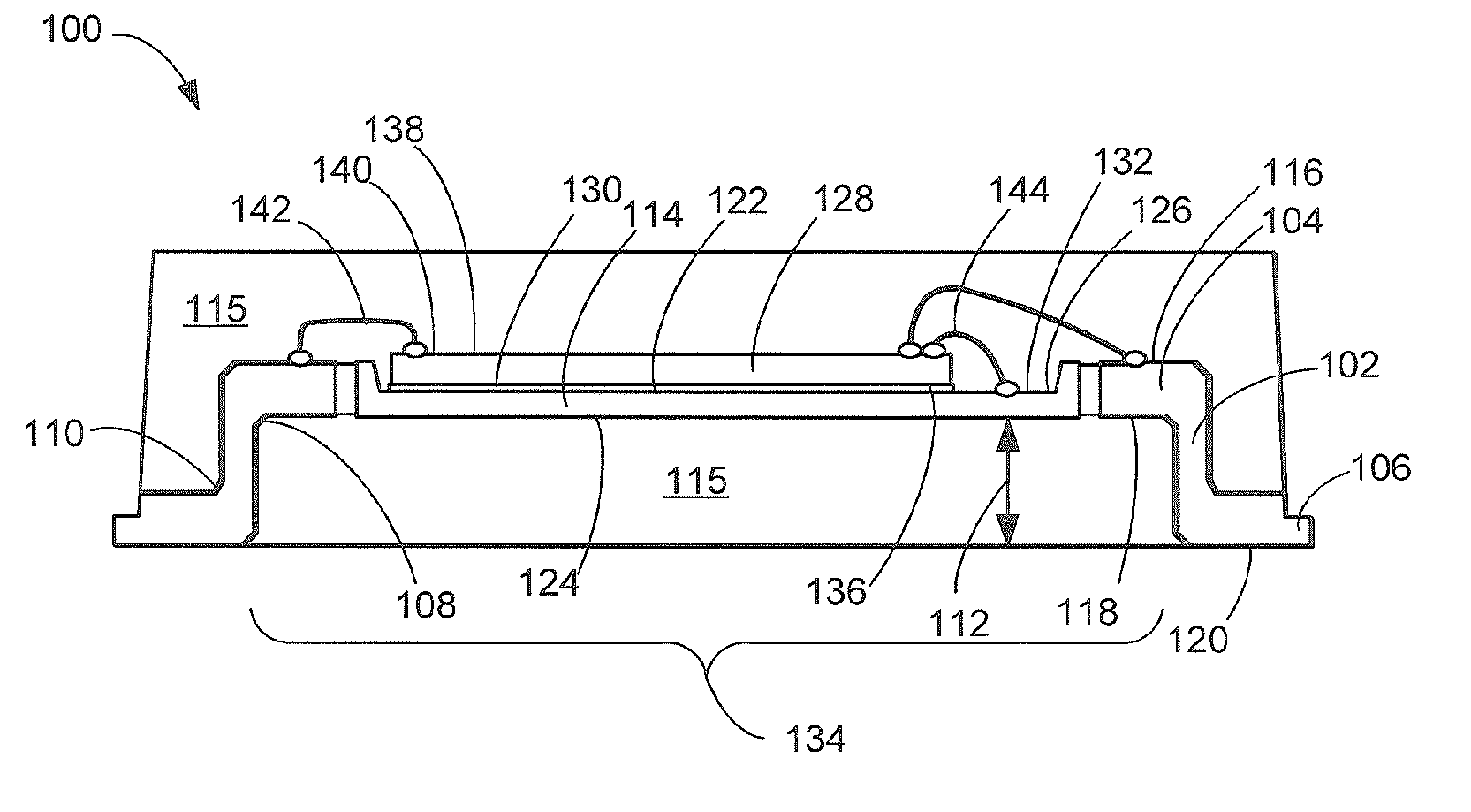
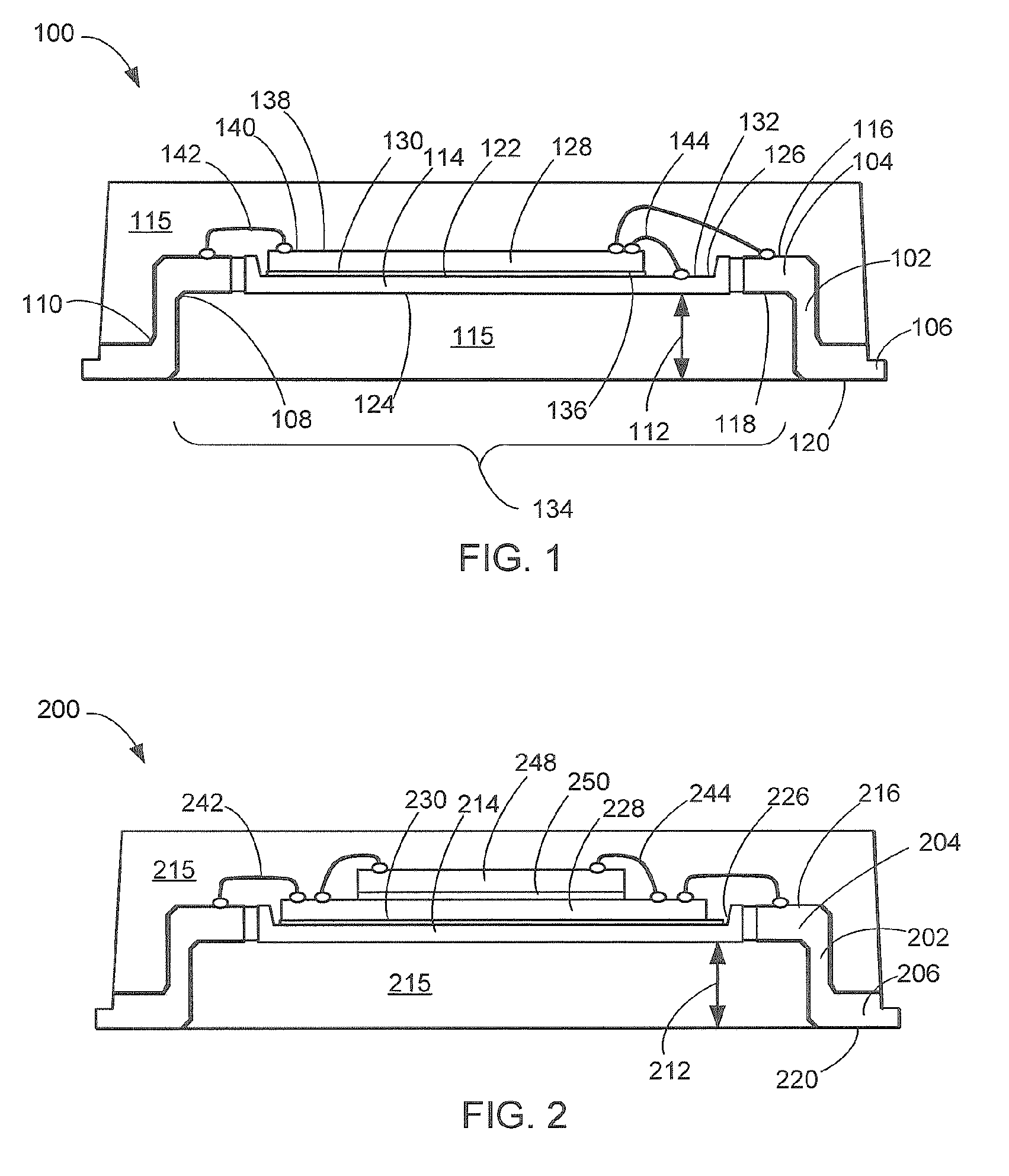
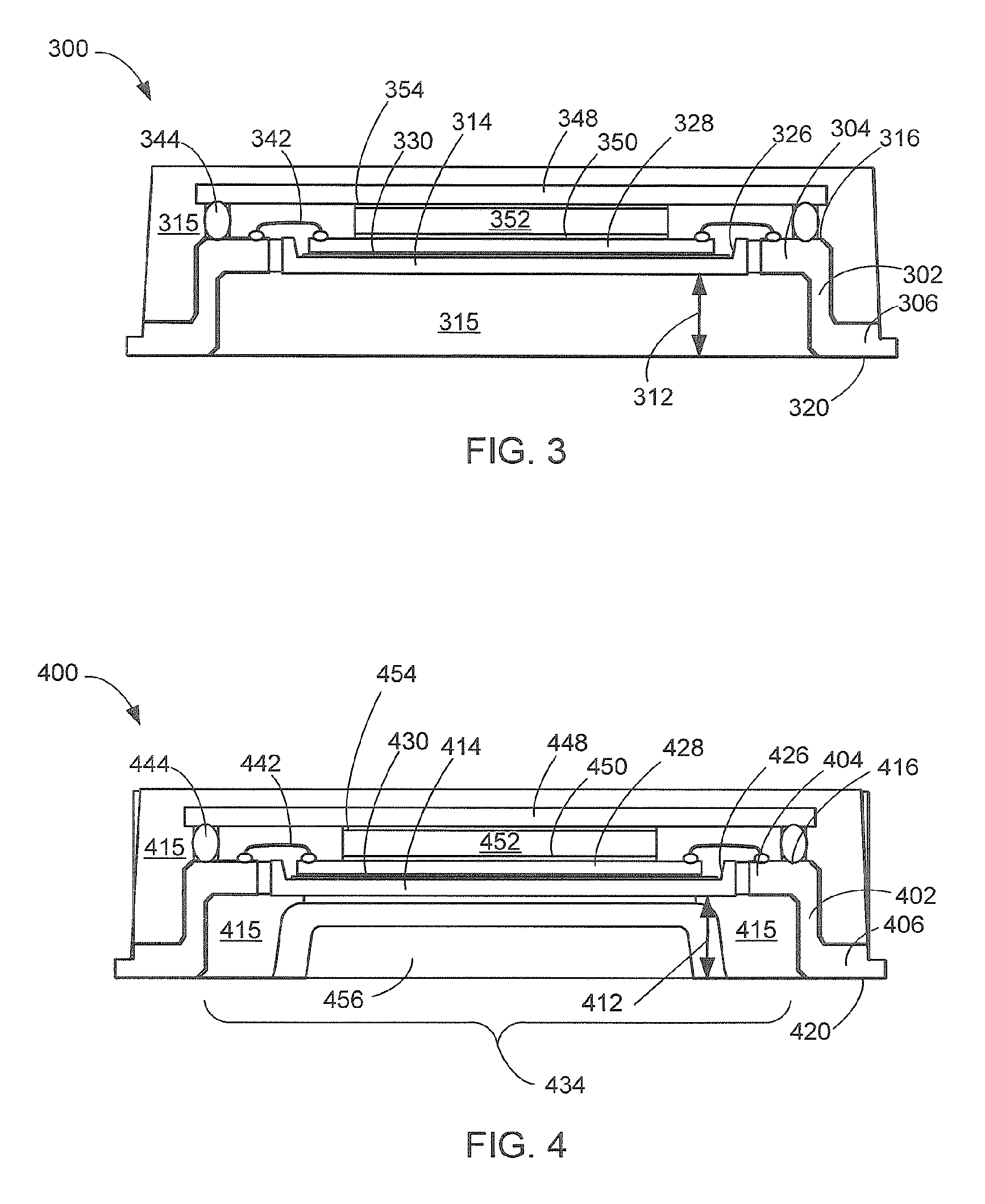
A non-leaded integrated circuits package system is provided including etching differential height lead structures having inner leads at a paddle height, providing mold locks at the bending points of the differential height lead structures, etching an elevated paddle at a same height as the inner leads, mounting a first integrated circuit on the elevated paddle, and electrically connecting first electrical interconnects between the first integrated circuit and the inner leads.

Description

CROSS-REFERENCE TO RELATED APPLICATION(S) [0001] This application claims the benefit of U.S. Provisional Patent Application Ser. No. 60 / 653,030 filed Feb. 14, 2005, and the subject matter thereof is hereby incorporated herein by reference thereto.TECHNICAL FIELD [0002] The present invention relates generally to integrated circuit package and more particularly to quad flat non-leaded packages. BACKGROUND ART [0003] Modern consumer electronics, such as cellular phones, digital cameras, and music players, are packing more integrated circuits into an ever shrinking physical space with expectations for decreasing cost. Numerous technologies have been developed to meet these requirements. Some of the research and development strategies focus on new package technologies while others focus on improving the existing and mature package technologies. Research and development in the existing package technologies may take a myriad of different directions. This packaging excerpt limits the discus...

Claims


Application Information

Patent Timeline
IPC IPC(8): H01L23/495
CPCH01L23/3107H01L23/49503H01L23/49548H01L23/49575H01L2224/16H01L2224/32145H01L2224/32245H01L2224/48091H01L2224/48145H01L2224/48247H01L2224/48257H01L2224/48464H01L2224/48465H01L2224/73265H01L2924/01015H01L2924/01029H01L2924/01047H01L2924/01078H01L2924/01079H01L2924/01082H01L2924/15153H01L2924/15165H01L2924/00014H01L24/32H01L24/48H01L2924/01023H01L2924/00H01L2224/32257H01L2224/45144H01L2224/45147H01L2924/3512H01L2924/00012H01L2224/45139H01L2224/451H01L2924/181H01L24/45H01L24/73H01L2924/14H01L2224/16245H01L2224/49109H01L2224/85439H01L24/49H01L2924/00011H01L2924/00015H01L2224/05599H01L2224/0401H01L2224/45015H01L2924/207
Inventor ONG, YOU YANG
Owner STATS CHIPPAC LTD
Learn More