
Remote controller sweat installation

a remote controller and sweat technology, applied in the direction of pulse technique, instruments, coding, etc., can solve the problem that sweat could easily get stuck in the pores of the remote controller, and achieve the effect of rapid vaporization of swea

Inactive Publication Date: 2006-08-10
CHIEN HUNG WEN
View PDF11 Cites 8 Cited by
  • Summary
  • Abstract
  • Description
  • Claims
  • Application Information

AI Technical Summary

Benefits of technology

[0006] The primary purpose of the present invention is to provide a remote controller sweat installation for rapid vaporization of sweat by taking advantage of capillary attraction.

Problems solved by technology

However, those pores relate to simple through holes and sweats could easily get stuck in those pores 11 due to surface tension to prevent evaporating those sweats.

Method used


Image

  • Remote controller sweat installation
  • Remote controller sweat installation
  • Remote controller sweat installation

Examples


Embodiment Construction

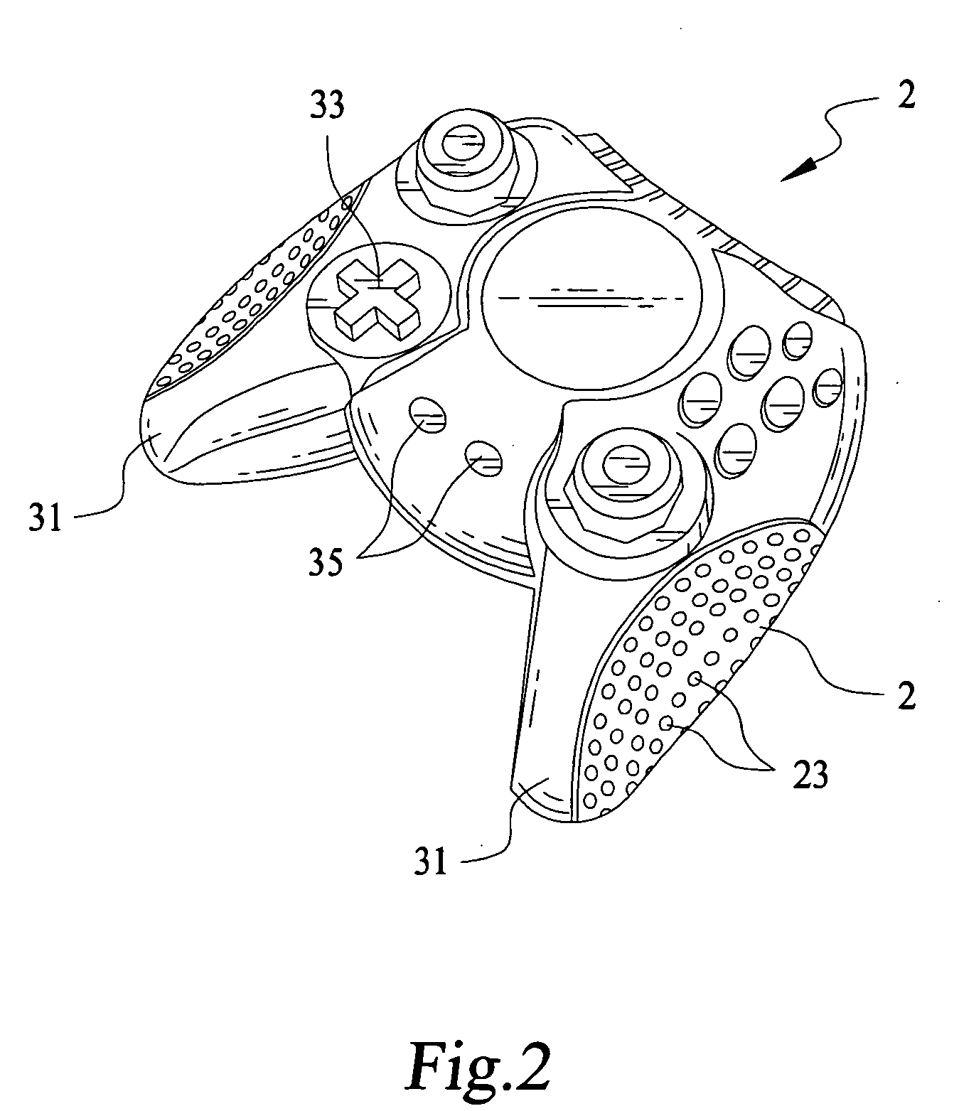
[0011] Referring to FIGS. 2 and 3, a remote controller sweat installation of the present invention is comprised of multiple sweat pores 23 arranged at equal spacing from one another on a surface 21 of a controller 2 where contacts both hands of the user. Multiple protruding tubes 25 are disposed on the inner edge of the controller 2 in relation to those pores 23. Each tube 25 contains a capillary 26 connecting through its corresponding pore 23.

[0012] Sweats from the hands of user holding the remote controller 2 are vaporized through those pores 23, capillaries 26, and terminals of those tubes 25 in sequence thanks to the capillary attraction provided by those capillaries 26.

[0013] As illustrated in FIGS. 2 and 3, the remote controller 2 relates to a TV game controller adapted with a pair of grips 31 for the user to hold on to. Multiple sweat pores 23 are arranged at equal spacing from on another on the surfaces where contact both hands of the user. Multiple protruding tubes 25 are...


PUM


Abstract

A remote controller sweat installation comprised of multiple sweat pores arranged at equal spacing on the surface of the controller where contacts hands of its user and multiple protruding tubes disposed on the inner edge of the controller in relation to those pores with each tube containing a capillary connecting through its corresponding pore for the sweat from the hands of the controller user to be soonest vaporized through pores, capillaries, and terminals of tubes in sequence by taking advantage of the capillary attraction.

Description

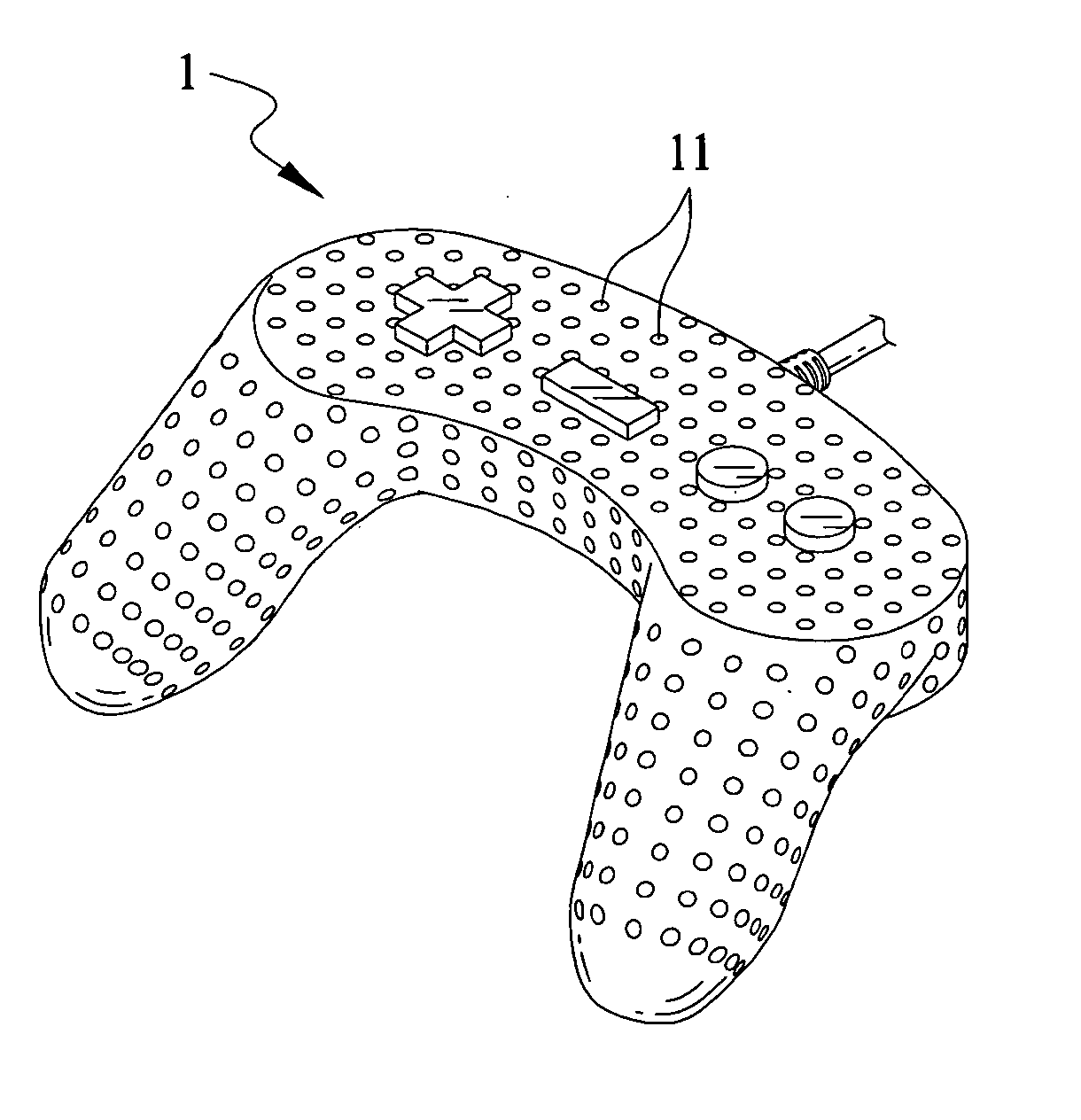
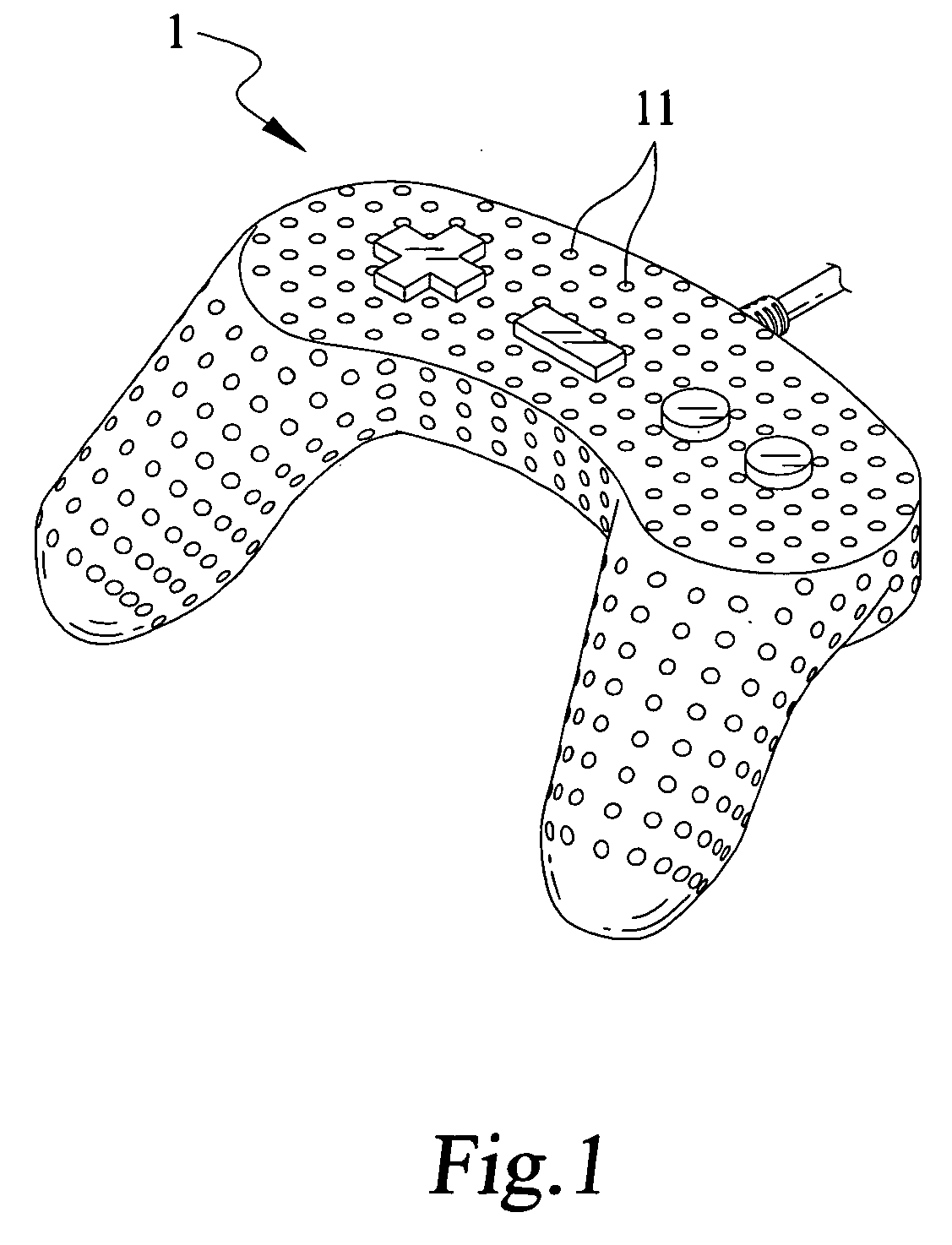
BACKGROUND OF THE INVENTION [0001] (a) Field of the Invention [0002] The present invention is related to a remote controller sweat installation, and more particularly to one that achieves rapid vaporization of sweat by taking advantage of capillary attraction. [0003] (b) Description of the Prior Art [0004] There is the absence of any construct to dispel sweats from the hands of the user of a remote controller, e.g., a TV game controller or a mouse, of the prior art. Sweats from hands thus all over the surface of the controller make the controller sticky to allow easy holding. [0005] An improvement has been developed as illustrated in FIG. 1 of the accompanying drawings by having provided multiple sweat pores 11 arranged at equal spacing from one another on the surface of the controller 1 to dispel sweats through those pores 11 into the controller 1 to be vaporized therein. However, those pores relate to simple through holes and sweats could easily get stuck in those pores 11 due to ...

Claims


Application Information

Patent Timeline
Patent Type & Authority Applications(United States)
IPC IPC(8): A63F13/00H03K17/94H05K7/20
CPCA63F13/02A63F13/06A63F2300/1043A63F2300/204A63F13/98A63F13/24A63F2300/663A63F13/92
Inventor CHIEN, HUNG WEN
Owner CHIEN HUNG WEN
Learn More