
Method and system for production of dynamic laser-induced images inside gaseous medium

a laser-induced image and gaseous medium technology, applied in the direction of laser beam welding apparatus, manufacturing tools, welding/soldering/cutting articles, etc., can solve the problem of small damage to the transparent material visibl

Inactive Publication Date: 2006-08-10
TROITSKI IGOR
View PDF16 Cites 7 Cited by
  • Summary
  • Abstract
  • Description
  • Claims
  • Application Information

AI Technical Summary

Benefits of technology

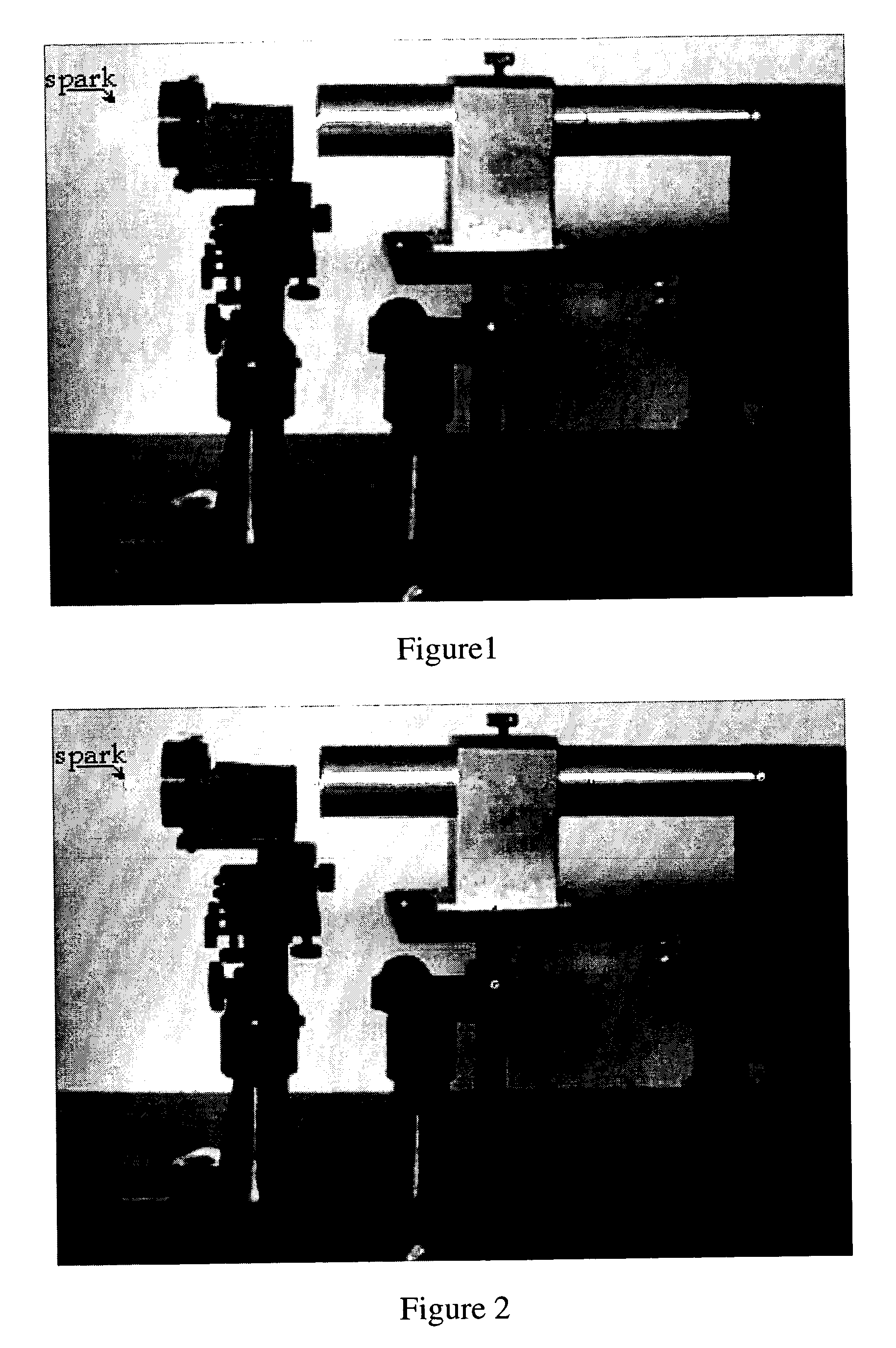
[0038]FIG. 1 shows a photo of an air breakdown spark produced by single mode second harmonic of Nd-YAG laser radiation focused by lens with short focal length (35 mm).
[0039]FIG. 2 shows a photo of an air breakdown spark produced by single mode second harmonic of Nd-YAG laser radiation focused by lens with short focal length (35 mm). The spark of this Figure was produced by laser radiation with pulse energy which is smaller than the energy used for production of the spark of FIG. 1.
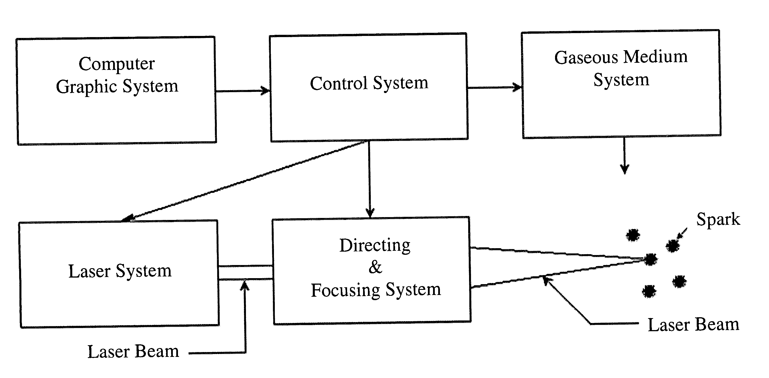
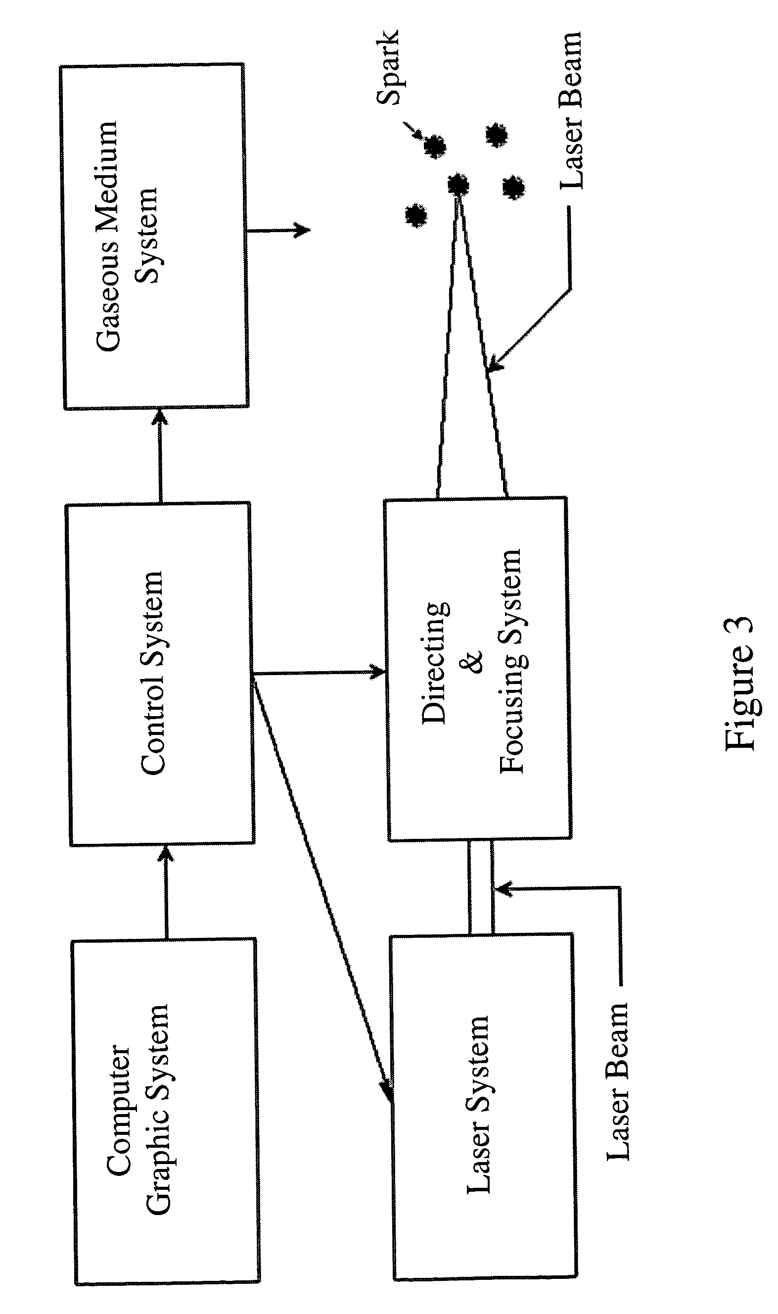
[0040]FIG. 3 illustrates in block-diagram form a system for production of dynamic laser-induced images inside gaseous medium. Computer graphic system transforms an image into point arrangements and transfers this information to the control system, which controls the laser system, and systems for directing and focusing laser radiation at the predetermined points of the gaseous medium. Simultaneously, the control system transfers information into gaseous medium system which creates and controls gaseous

Problems solved by technology

The breakdown creates a small damage of the transparent material which is visible because it scatters the exterior light.
These laser-induced damage images are stationary in time, they are created for ever and can be destroyed by destruction of the transparent material only.
However, the breakdown, creating a material damage, simultaneously, creates a bright flash of white light, the appearance of which leads to the term “spark”.

Method used


Image

  • Method and system for production of dynamic laser-induced images inside gaseous medium
  • Method and system for production of dynamic laser-induced images inside gaseous medium
  • Method and system for production of dynamic laser-induced images inside gaseous medium

Examples


Embodiment Construction

[0041] The invention comprises a method and a system for production of dynamic laser-induced images inside gaseous medium by using sparks generated by the laser breakdown.

[0042] The principal concepts of the invention are based on the following pieces of evidence of laser-induced breakdown in gases: [0043] 1) The laser-induced breakdown is generated at the focal area of pulsed laser radiation. [0044] 2) The breakdown occurs only after threshold irradiance is achieved. Below the threshold value, virtually no effects are observed. [0045] 3) Simultaneously with the breakdown occurs a bright flash of white light, the appearance of which leads to the term “spark”. [0046] 4) The spark is accompanied by production of charged particles, absorption of the laser light, and reradiation of light from the spark. [0047] 5) The breakdown in gases has two general stages: (1) the production of the initial ionization, and (2) the subsequent cascade by which the ionization grows and a spark is observ...


PUM

PropertyMeasurementUnit
focal lengthaaaaaaaaaa
thickaaaaaaaaaa
lengthaaaaaaaaaa

Abstract

One or more embodiments of the invention comprise a method for creating breakdown sparks of needed brightness, sizes and duration by controlling pulse energy, pulse width, pulse duration, wavelength, temporal shape and space structure of laser radiation. Method for transformation of a dynamic image into succession of points arrangements for gaseous medium, at which breakdown sparks are produced, is disclosed. One or more embodiments of the invention comprise a method and a system for production of dynamic laser-induced images inside gaseous medium. These images are configurations of sparks which are changed by controlling the points of the gaseous medium at which the laser breakdowns are generated.

Description

FIELD OF THE INVENTION [0001] The present invention relates to methods for producing laser-induced images inside transparent medium by using pulsed laser radiation. BACKGROUND OF THE INVENTION [0002] A number of techniques for creation of images inside solid transparent substrates by using pulsed laser radiation are well known. [0003] The publication disclosing such techniques is the Russian invention # 321422 to Agadjanov et. al., published on Nov. 16, 1970 (#140454529-33). The invention concerns a method of manufacturing decorative products inside a transparent material by changing the material structure by laser radiation. As disclosed, by moving a material relative to a focused laser beam, it is possible to create a drawing inside the material. [0004] U.S. Pat. No. 4,092,518 to Merard discloses a method for decorating transparent plastic articles. This technique is carried out by directing a pulsed laser beam into the body of an article by successively focusing the laser beam in...

Claims


Application Information

Patent Timeline
Patent Type & Authority Applications(United States)
IPC IPC(8): B23K26/00
CPCB23K26/0635B23K26/4035B44F1/00C03C23/0025B23K26/0624B23K2103/32B23K2103/50
Inventor TROITSKI, IGOR
Owner TROITSKI IGOR
Learn More