
Detection Apparatus and Detection Method for Plasmon Resonance and Fluorescence

a detection apparatus and fluorescence technology, applied in the field of detection apparatus and detection method of plasmon resonance and fluorescence, can solve the problems of difficult to measure the response speed with high sensitivity or a concentration of low-molecular weight compounds, and the inability to specify which site is cancerous

Inactive Publication Date: 2006-08-03
CANON KK
View PDF5 Cites 45 Cited by
  • Summary
  • Abstract
  • Description
  • Claims
  • Application Information

AI Technical Summary

Benefits of technology

[0009] An object of the present invention is to provide a de

Problems solved by technology

However, the fluorescence immunoassay method can measure the concentration of the target substance with high sensitivity but fails to measure a reaction speed.
On the other hand, the plasmon resonance method can measure the response speed but it is somewhat difficult to measure the response speed with high sensitivity or a concentration of a low-molecular weight compound.
For example, the oncogenic markers such as CEA and CA19-9 are formed of cells of a plurality of organs such as stomach, large bowel, pancreas, and lung, so that there has arisen such a problem that it is impossible to specify which site is cancerous only by measuring one species of marker.

Method used


Image

  • Detection Apparatus and Detection Method for Plasmon Resonance and Fluorescence
  • Detection Apparatus and Detection Method for Plasmon Resonance and Fluorescence
  • Detection Apparatus and Detection Method for Plasmon Resonance and Fluorescence

Examples


embodiment 1

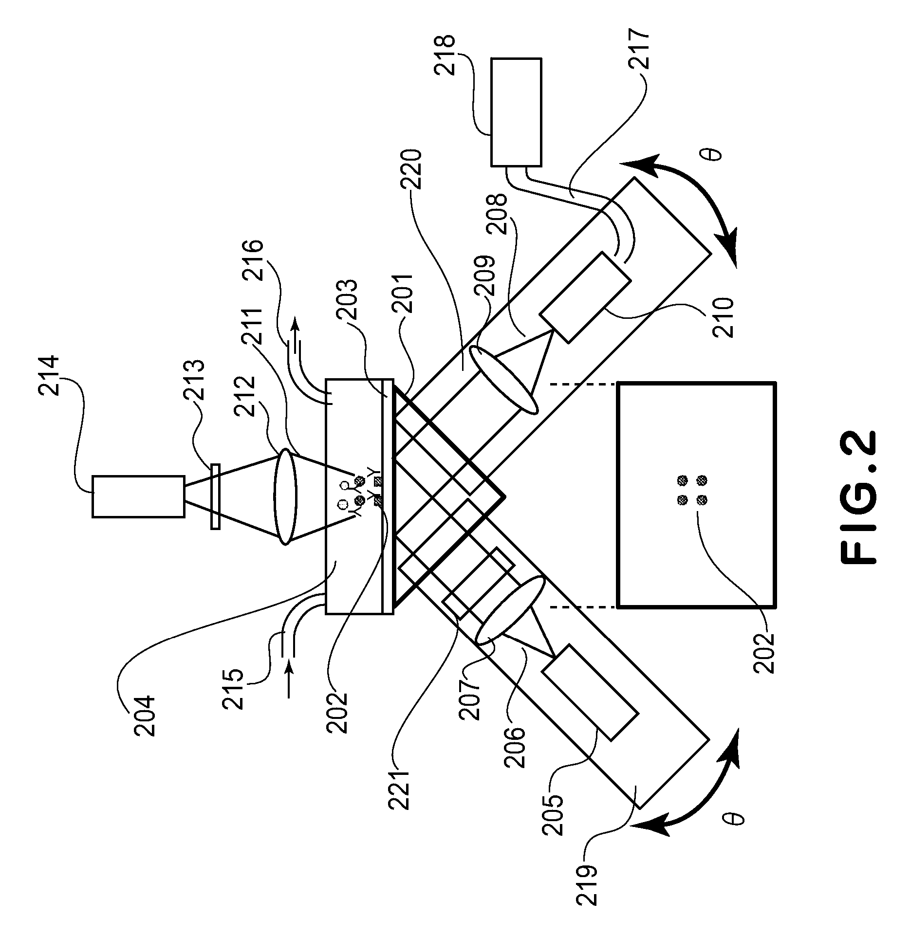
[0076] Referring to FIG. 2, onto a plane A of a prism 201 (“BK7”; A=28.3 mm, B=C=20 mm), an index matching fluid (“F-IMF-105”, mfd. by Newport Corp.) having the same refractive index as the prism 201 was applied and a substrate 203 on which a metal array 202 comprising a plurality of dots (metal films) each having a diameter of 100 μm was formed was caused to hermetically contact the prism 201.

[0077] To the substrate 203, a transparent reaction cell 204 in which a specimen and a washing liquid were introduced was bonded. As a light source 205, a laser diode (“DL3038-033”, mfd. by SANYO Electric Co., Ltd.) was used. As a collimating lens 207, a planoconvex lens (mfd. by SIGMA KOKI Co., Ltd.; diameter 5 mm) was used. As a filter 221, a polarizing filter (“SPF-30C-32”, mfd. by SIGMA KOKI Co., Ltd.) was used.

[0078] This incident optical system was fixed on an arm 219. As an optical sensor 210, a CCD area image sensor (“S7030-0906”, mfd. by Hamamatsu Photonics K.K.) was used. As a coll...

embodiment 2

[0098] Hybridization measurement of DNA was performed by using the optical system employed in Embodiment 1.

[0099] On the surface of each metal arrays, streptavidin was deposited, and 4 species of biotin-modified 20-mer DNA were adsorbed to prepare a nucleic acid sensor.

[0100] Detailed description will be made with reference to FIGS. 5(a) to 5(d).

[0101] As shown in FIG. 5(a) (plan view), on a 2×2 metal array 402 formed on a substrate 401, 4 species of biotin-modified 20-mer DNAs were fixed and subjected to the following protocol (procedure).

[0102] Fixation of different ligands on the metal array was performed according to a method described in U.S. Pat. No. 6,194,223.

[0103] (1) A specimen liquid in which four species (A*, B*, C* and D*) of composites 403, fluorescence-labeled with Cy5 dye, comprising DNA 405 (probe P) having fixed base sequence as shown in FIG. 5(b) and corresponding ligand DNAs (target T1, 20-mer as shown in FIG. 4(c) and four species of 20-mer DNAs (target T2;...


PUM

PropertyMeasurementUnit
Angleaaaaaaaaaa
Fluorescenceaaaaaaaaaa
Resonanceaaaaaaaaaa

Abstract

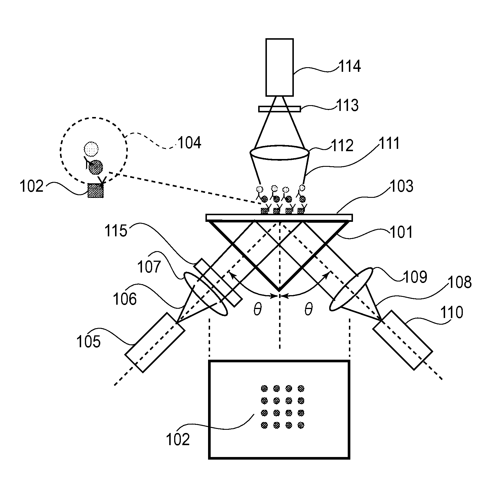
A plurality of different ligands are fixed on a metal array including a plurality of metal films formed on a substrate and are irradiated with light from a rear surface of the substrate to measure surface plasmon resonance and fluorescence based on evanescent wave at the same time, thus permitting screening for concurrently measuring a plurality of items with accuracy.

Description

FIELD OF THE INVENTION AND RELATED ART [0001] The present invention relates to a detection apparatus and a detection method for quickly finding molecules leading to pathogenic bacteria to perform diagnosis by screening a plurality of biomolecules such as protein and DNA at the same time. [0002] In blood, there are a plurality of makers for specific diseases such as cancer, hepatitis, diabetes, and osteoporosis. When a person contracts a disease, a concentration of a specific protein is increased compared with that in ordinary times. It is possible to early detect means disease by monitoring the markers even in ordinary times, so that the monitoring of the markers is expected as a next-generation medical technology. [0003] One of methods for analyzing raw and crude protein is based on a sensor for identifying a specific compound by utilizing a biological ligand-target substance interaction. A combination of ligand-target substance may include an antigen-antibody composite utilizing a...

Claims


Application Information

Patent Timeline
IPC IPC(8): G01J3/30G01N21/55G01N33/543C12Q1/68G01N21/27G01N21/41G01N21/64G01N21/78G01N33/53G01N37/00
CPCG01N21/05G01N21/553G01N21/6428G01N21/6452G01N21/6456G01N21/648G01N33/574G01N2021/1772G01N2021/6439
Inventor NISHIUMA, SATORU
Owner CANON KK
Learn More