Electrode structure of planar lamp

a planar lamp and electrode structure technology, applied in the direction of discharge tube/lamp details, discharge tube luminescnet screens, gas-filled discharge tubes, etc., can solve the problem of still dim light in some portions, achieve light uniformity of planar lamps, and increase power-input area

Inactive Publication Date: 2006-08-03
ZIPPY TECH
View PDF7 Cites 0 Cited by
  • Summary
  • Abstract
  • Description
  • Claims
  • Application Information

AI Technical Summary

Benefits of technology

[0004] The primary objective of the present invention is to solve the aforementioned problem. The present invention adopts an electrically conductive element, which traverses the bending channels of the planar lamp, to increase the power-input area to enable every electrically conductive channel to create gas-discharge and excite the fluorescent material to emit light so that the light uniformity of the planar lamp can be achieved.
[0005] Another objective of the present invention is to realize the electrically-conductive element via applying an adhesive carbon-fiber patch with an electrically-conductive paste to the discharge electrodes in order to reduce the manufacture cost and promote the quality and the manufacture efficiency.

Problems solved by technology

Furthermore, as shown in FIG. 1, in both the internal-electrode type and the external-electrode type, the electrodes are usually disposed in both ends of the planar lamp; as the electrodes of both ends of the planar lamp have many bending channels, a higher initial voltage for discharge is needed in the portions of the sharp corners of bending channels; however, the light in some portions is still dim as the distance between the electrodes is too long.

Method used


Image

  • Electrode structure of planar lamp
  • Electrode structure of planar lamp
  • Electrode structure of planar lamp

Examples


Embodiment Construction

[0013] In cooperation with the attached drawings, the detailed description and the technical contents of the present invention will be stated below.

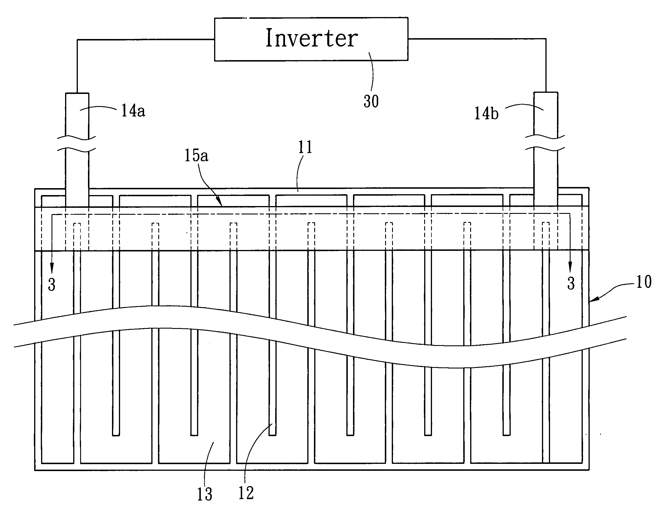
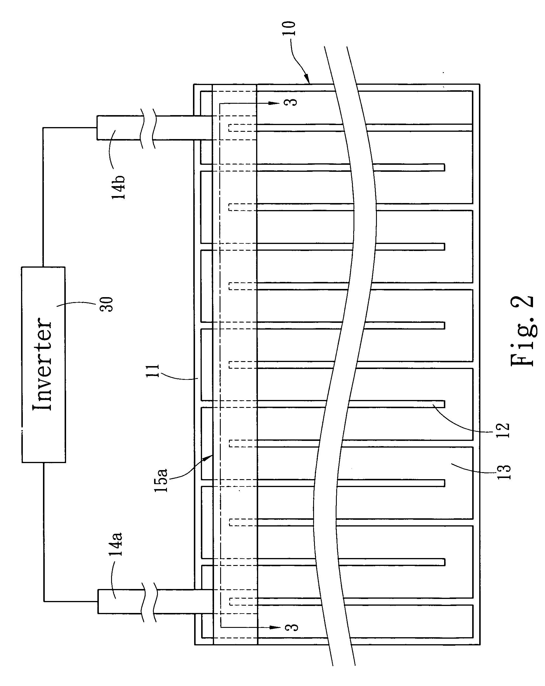
[0014] Refer to FIG. 2 and FIG. 3 schematic diagrams showing the disposition of the discharge electrode 14a and 14b of the planar lamp 10. The present invention applies to a planar lamp 10, which has a gas-discharge cavity 11 with at least one bending channel 13. The bending channel 13 can be formed via partitioning the interior of the gas-discharge cavity 11 with separators 12. The interior of the gas-discharge cavity 11 is equipped with a fluorescent material and a discharge gas, and metallic discharge electrodes 14a and 14b are disposed on the external wall of the gas-discharge cavity 11. The discharge electrodes 14a and 14b are electrically connected to an inverter 30. In the present invention, the discharge electrodes 14a and 14b are installed on the surface of at least one external wall of the gas-discharge cavity 11, and an elect...


PUM


Abstract

The present invention discloses an improved electrode structure of planar lamp, which applies to the planar lamp that has a gas-discharge cavity with at least a bending channel and with a discharge gas and a fluorescent material equipped thereinside. Via disposing an electrically conductive element, which traverses the bending channels, onto the discharge electrodes on the external wall of the gas-discharge cavity, the input area of the power output by the discharge electrodes is increased, and thus, the light uniformity of the planar lamp is achieved.

Description

FIELD OF THE INVENTION [0001] The present invention relates to an improved electrode structure of planar lamp, particularly to one, wherein an electrically-conductive element that traverses the bending channels of the planar lamp is adopted to increase the input area of the power output by the discharge electrodes so as to achieve the light uniformity of the planar lamp. BACKGROUND OF THE INVENTION [0002] What the planar fluorescent lamp lays most stress on is to achieve the uniform distribution of light, and the operational principle of the conventional planar gas-discharge lamp, which is used as the backlight source, is that with an inverter providing the power, the fluorescent material coated on the light-emitting side is excited to emit light via the means of gas (usually an inert gas) discharging. For the similar technology, please refer to R.O.C. Patent POublication No. 521300 “Dielectric Barrier-Type Discharge Lamp With Support Element Between Bottom Plate And Cover Plate”. A...

Claims


Application Information

Patent Timeline
Patent Type & Authority Applications(United States)
IPC IPC(8): H01J61/04H01J17/04
CPCH01J61/067H01J61/307H01J65/00H01J65/046
Inventor CHOU, CHIN-WENCHENG, YING-NAN
Owner ZIPPY TECH
Why Eureka
Try Eureka