Circuits and methods for synchronizing multi-phase converter with display signal of LCD device

a multi-phase converter and display signal technology, applied in static indicating devices, cathode-ray tube indicators, instruments, etc., can solve the problems of large ripple on the power line, degrade the signal/noise integrity of the system, and affect the quality of the displaying picture image, so as to eliminate the phenomenon of interference (or moire)

Inactive Publication Date: 2006-07-27
BEYOND INNOVATION TECH
View PDF6 Cites 40 Cited by
  • Summary
  • Abstract
  • Description
  • Claims
  • Application Information

AI Technical Summary

Benefits of technology

[0017] A main object of the present invention is to provide a controller for controlling at least two DC / DC converters, wherein the DC / DC converters supply energy to multiple loads, such as a LCD device including a gate driver, a source driver, a gamma voltage generator, and a timing controller, which is adapted to synchronize the converters with a display signal so as to substantially eliminate an interference (or moire) phenomenon in the horizontal or vertical direction of the display resulted from the difference frequency between the frequency of the display signal and the switching frequency of the DC / DC converter.
[0018] Another object of the present invention is to provide a multi-phase converter driving circuit for supplying energy to multiple loads, such as a LCD device including a gate driver, a source driver, a gamma voltage generator, and a timing controller, which is adapted to synchronize the multi-phase converter with a display signal so as to substantially eliminate an interference (or moire) phenomenon in the horizontal or vertical direction of the display resulted from the difference frequency between the frequency of the display signal and the switching frequency of the DC / DC converter.
[0019] Another object of the present invention is to a multi-phase converter driving circuit for supplying energy to multiple loads, such as a LCD device including a gate driver, a source driver, a gamma voltage generator, and a timing controller, which reduces instantaneous high current ripples and noises caused by controlling the switches on and off durations in the multi-phase converter driving circuit.
[0020] Another object of the present invention is to provide a display device which utilizes a multi-phase converter driving circuit for supplying energy to multiple loads, such as a LCD device including a gate driver, a source driver, a gamma voltage generator, and a timing controller, which is adapted to synchronize the multi-phase converter with a display signal so as to substantially eliminate an interference (or moire) phenomenon in the horizontal or vertical direction of the display resulted from the difference frequency between the frequency of the display signal and the converter switching frequency.

Problems solved by technology

In other words, the quality of the displaying picture images will be affected by current ripples and noises caused by turning ON and turning OFF switches in the DC / DC converter.
Therefore, there is a large ripple on the power line.
The simultaneous turning on and off at the buck converter 301 cause noises on the power line which degrades the signal / noise integrity in the system.
However, the disadvantage is that the size of the circuit is increased, which in turn increases the system cost.
There are disadvantages regarding this conventional DC / DC converter circuitry for supplying energy to the LCD device.
As a result, when the DC / DC converter circuitry is utilized in practice for supplying energy to the LCD device, an interference (or moire) phenomenon in the horizontal or vertical direction of the display results from the difference frequency between the switching frequency and the frequency.

Method used


Image

  • Circuits and methods for synchronizing multi-phase converter with display signal of LCD device
  • Circuits and methods for synchronizing multi-phase converter with display signal of LCD device
  • Circuits and methods for synchronizing multi-phase converter with display signal of LCD device

Examples


Embodiment Construction

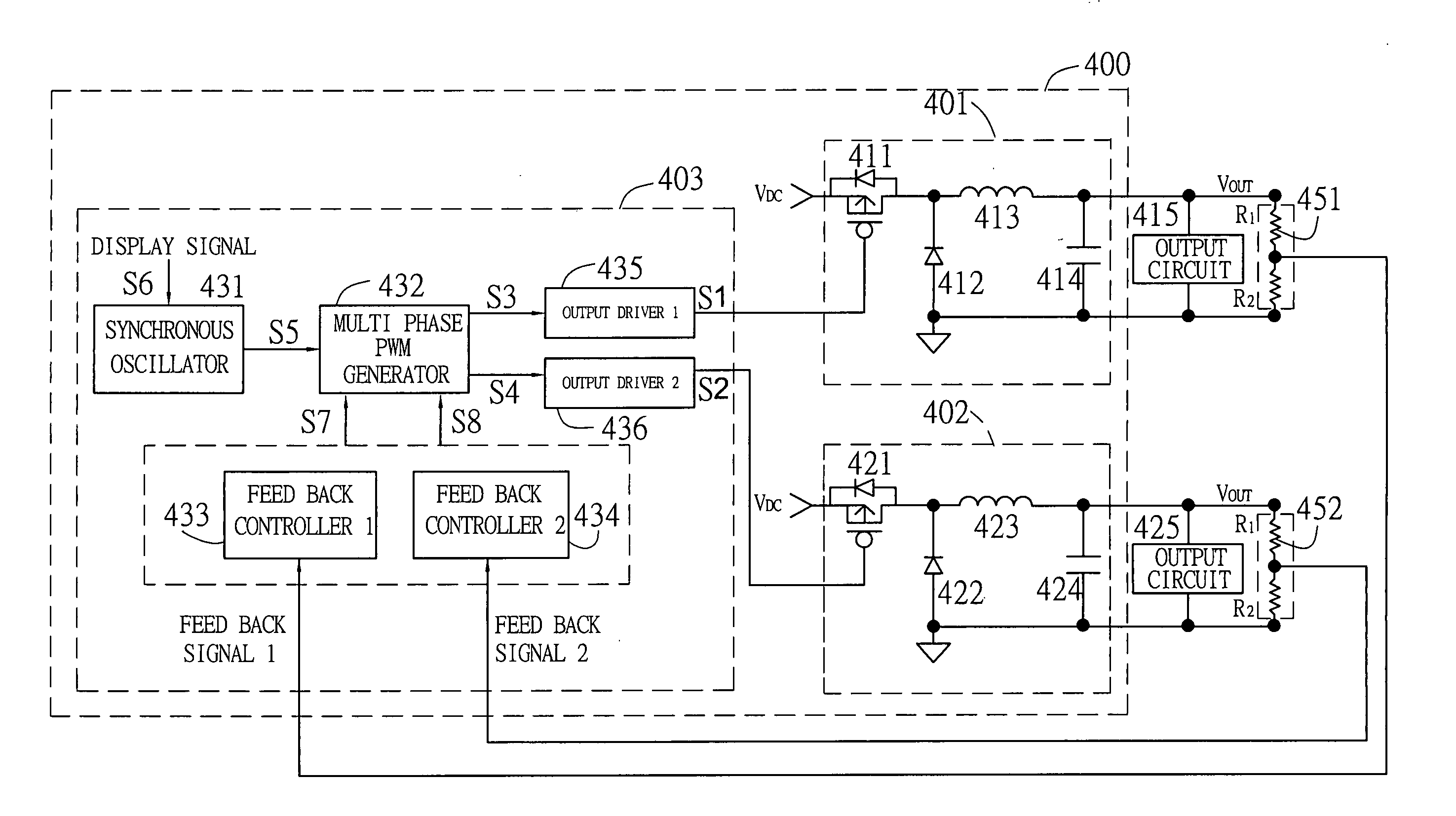
[0033] The following examples use a buck converter to illustrate the embodiments of the invention. Nevertheless, the DC / DC converter of this invention is not limited to a buck converter. However, the DC / DC converter circuitry could use a boost converter, a push-pull converter, a forward converter, a flyback converter, a half-bridge converter, or a full-bridge converter instead of the buck converter.

[0034] Referring to FIG. 4 of the drawings, a schematic view of DC / DC converter circuitry according to a preferred embodiment of the present invention is illustrated. All output circuits 415, 425 are synchronized. The DC / DC converter circuitry 400 comprises a first DC / DC converter 401, a second DC / DC converter 402, and a controller 403. In this embodiment, the first DC / DC converter 401 and the second DC / DC converter 402 are buck converters. The first DC / DC converter 401 and the second DC / DC converter 402 are coupled to the controller 403. The controller 403 provides control signals S1, S...


PUM


Abstract

A controller for controlling at least two power circuits comprises a synchronous oscillator and a multi-phase PWM controller. The synchronous oscillator receives a timing signal for generating a synchronous control signal in which the timing signal is synchronous to a display signal. The multi-phase PWM controller receives the synchronous control signal for generating at least two PWM signals. The at least two PWM signals are coupled to the at least two power circuits for driving the at least two power circuits respectively. The at least two PWM signals are synchronous to the timing signal and with a phase shift between the at least two PWM signals.

Description

BACKGROUND OF THE PRESENT INVENTION [0001] 1. Field of Invention [0002] The present invention relates to a converter driving circuit for supplying energy to multiple loads, such as a LCD device including a gate driver, a source driver, a gamma voltage generator, and a timing controller, and more particularly to a multi-phase converter driving circuit which is adapted to synchronize the multi-phase converter with a Display signal. Usually, the converters are applied to display devices, such as liquid crystal display monitors, liquid crystal display computers or liquid crystal display televisions. [0003] 2. Description of Related Arts [0004] Liquid crystal displays (LCD) are wildly employed in display devices, such as liquid crystal display monitors, liquid crystal display computers or liquid crystal display televisions. A driving circuit of a related art LCD device is described in U.S. Pat. No. 6,731,259. As shown in FIG. 1, which is a block diagram of a related art LCD device, the r...

Claims


Application Information

Patent Timeline
Patent Type & Authority Applications(United States)
IPC IPC(8): G09G3/36
CPCG09G3/3648G09G3/3696G09G5/18G09G2330/06
Inventor YU, CHUNG-CHECHIANG, WEN-CHIEHLEE, LI-MIN
Owner BEYOND INNOVATION TECH
Why Eureka
Try Eureka