
Frictional clutch for torque-restricted torsional power transmission between two reels of a hand-held device

a technology of torque restriction and frictional clutch, which is applied in the direction of couplings, manual label dispensers, labelling, etc., can solve the problems of inability to offer a bearing surface in circular form to the reel, difficulty in manufacturing spring rings, and impaired support of the reel, so as to simplify the manufacture of frictional clutches

Active Publication Date: 2006-07-27
SOC DITE SOC BIC
View PDF12 Cites 1 Cited by
  • Summary
  • Abstract
  • Description
  • Claims
  • Application Information

AI Technical Summary

Benefits of technology

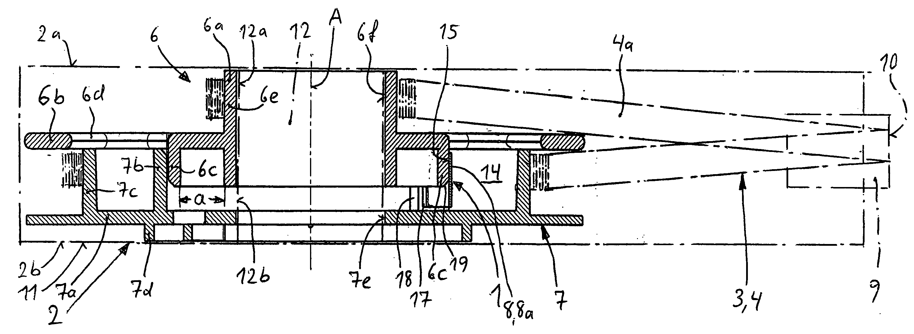
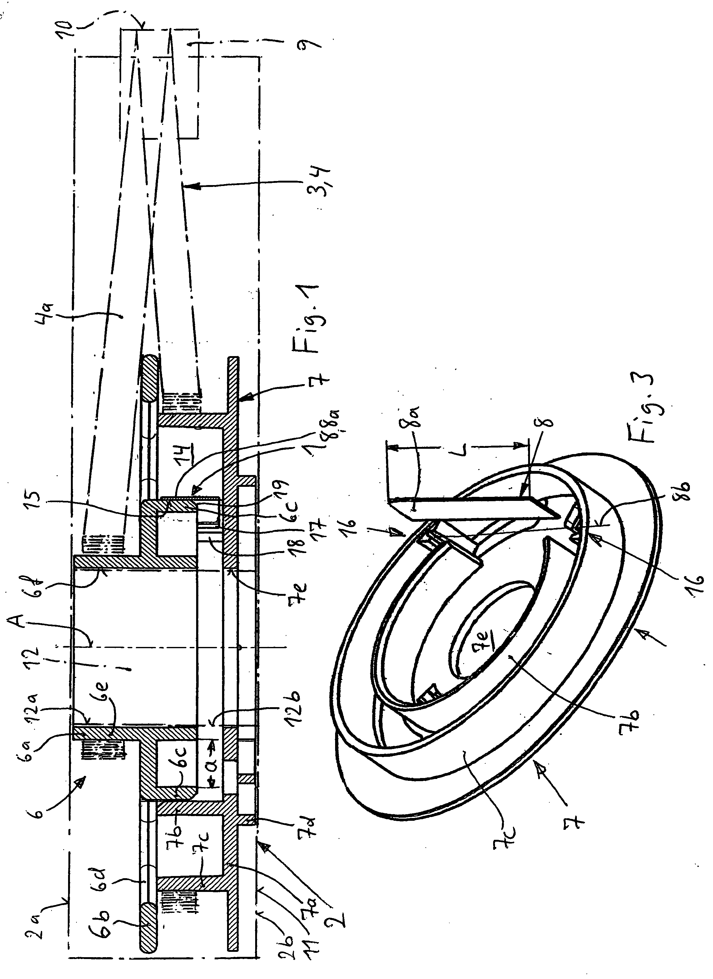
[0007] In one embodiment of the frictional clutch of the invention, the spring element is freed from the bearing function. The spring element of the embodiment of the invention has merely a frictional function and not a bearing function. It presses radially elastically against a preferably cylindrical circular ring surface of the other reel, whereby, for one, pivoting guidance at a certain torque is ensured and, for the other, slippage is ensured when torque is exceeded. Since the spring element does not perform any bearing function, it need not be adapted to the shape of any bearing surface, so that it can be of simple design, which is conducive to the aim of creating simple and inexpensive design.
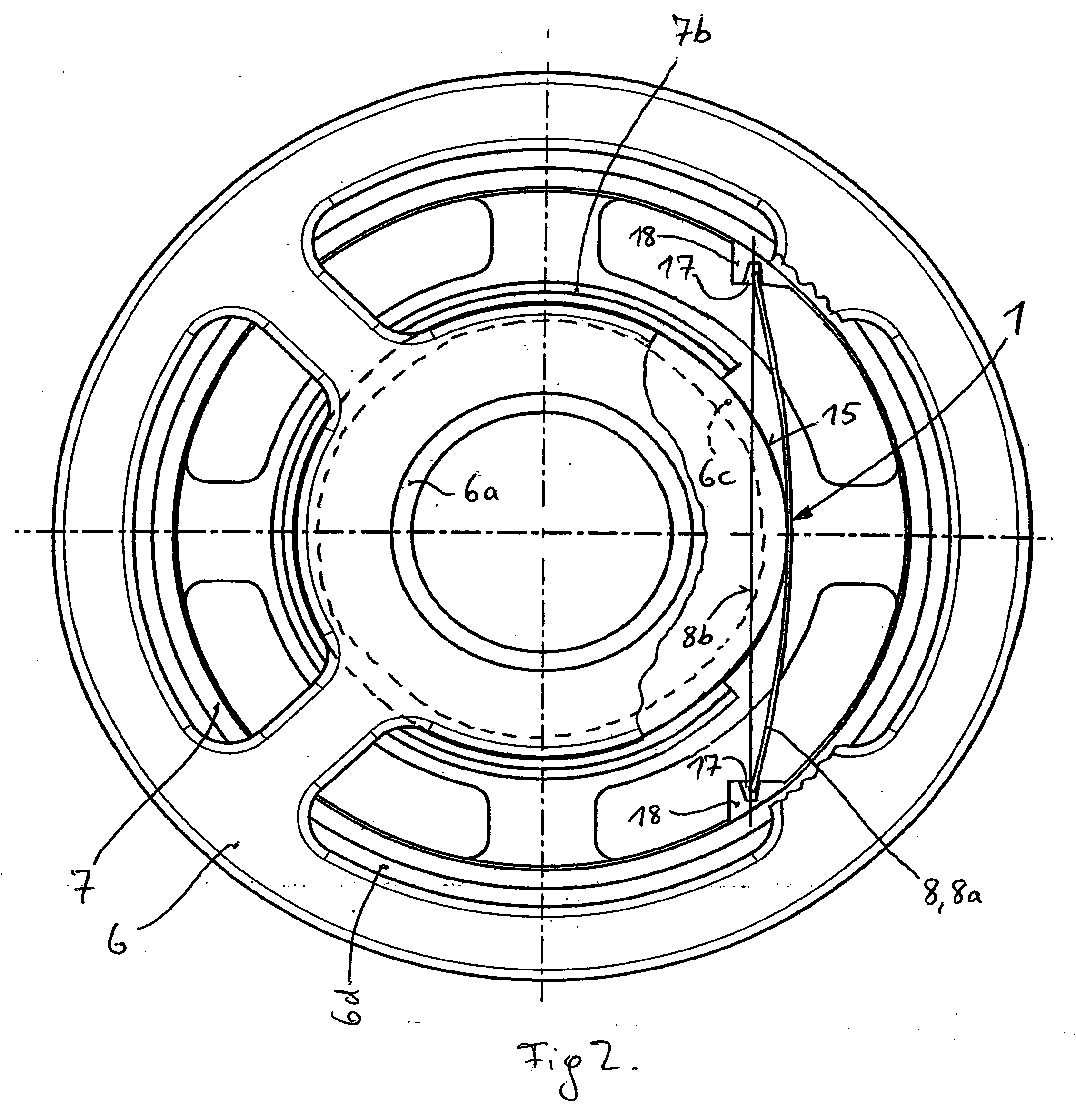
[0008] In order to design the spring element with favorable elasticity which remains the same over a long period of operation, longish or bar-like shape of the spring element is preferable, in particular in the form of a leaf spring which is supported in its end portions and presses elastically against the circular ring surface with its central portion. It is preferable to use a bar-like spring or a leaf spring, which extends in a straight fashion when in a stress-relieved condition and thus can be produced or prefabricated in a simple and inexpensive fashion. By radial bending out of the central portion of the bar-like or leaf spring, said portion can enter into frictional contact with the opposing circular ring surface, while the free end portions of the leaf spring are supported in the free space receiving them.
[0009] Another embodiment of the invention includes providing two support positions for ends of the bar-like spring element on a line secantially with respect to the cylindrical circular ring surface. During assembly, the bar or leaf-shaped spring element is bent out into the free space available far enough to abut on the cylindrical outer generated surface of the other reel in the event of an elastic restoring tension. In this embodiment, not only simple construction is ensured but also simple assembly and disassembly.

Problems solved by technology

By radial bending, the spring ring presses elastically against the cylindrical inner generated surface of the outer bearing member, as a result of which the frictional clutch is formed due to cumbersome running.
In said previously known frictional clutch, it is difficult to manufacture the spring ring in a form and size so as to form a circular ring-shaped bearing surface on which the reel can slide over a large surface.
There is a danger of the spring ring to relieve primarily into two opposite directions, so that it cannot offer a bearing surface in circular form to the reel located thereon.
As a result thereof, support of the reel can be impaired, for instance, by excessive movement clearance due to wear of the relatively small bearing surface portions.
As a result thereof, chattering can occur upon rotation of the reel, which is undesirable.

Method used


Image

  • Frictional clutch for torque-restricted torsional power transmission between two reels of a hand-held device
  • Frictional clutch for torque-restricted torsional power transmission between two reels of a hand-held device
  • Frictional clutch for torque-restricted torsional power transmission between two reels of a hand-held device

Examples


Embodiment Construction

[0016] The frictional clutch referred to by 1 in its entirety is designed by incorporating three components of a hand-held device 2 for transferring a film 3 from a backing tape 4 onto a substrate, namely by incorporating a supply reel 6, a take-up reel 7 and a spring element 8. The backing tape 4 is wound up on the supply reel 6 so as to form a supply and extends to a wedge-shaped application member 9 having a wedge-shaped or slightly rounded application edge 10, around which the backing tape 4 is wound and extends to the take-up reel 7, onto which it is wound automatically when the hand-held device 2 is being used. The film 3 adheres to the outer side of the backing tape 4, and thus also to the outer side of the backing tape portion 4a extending from the supply reel 6 to the application edge 10. The application member 9 projects with its application edge 10 from the housing 11, which is represented in outlines and which comprises an outlet opening and an inlet opening for the back...


PUM


Abstract

An embodiment of the invention relates to a frictional clutch for a hand-held device for transferring a film from a backing tape onto a substrate. The frictional clutch in this embodiment includes a supply reel and a take-up reel rotatably mounted coaxially to each other, one of the reels including a free space bordered by a circular ring surface of the other reel, a spring element being disposed in the free space, with the spring element pressing elastically against the circular ring surface. In one embodiment of the frictional clutch, the free space is located radially outside the convex circular ring surface and the spring element is biased radially towards inside against the circular ring surface.

Description

CROSS-REFERENCE To RELATED APPLICATION [0001] This application is a continuation of PCT Application No. PCT / EP03 / 11350, filed on Oct. 14, 2003, which claims priority to European Patent Application 02 026 099.8, filed on Nov. 22, 2002. The entire contents of these two applications is expressly incorporated herein. FIELD OF THE INVENTION [0002] The invention relates to a frictional clutch for a hand-held device for transferring a film from a backing tape onto a substrate. BACKGROUND OF THE INVENTION [0003] Such a frictional clutch serves for creating drive adjustment for a take-up reel of a hand-held device for transferring a film from a backing tape onto a substrate, said take-up reel being driven so forcedly that the backing tape portion being supplied to the take-up reel is always slightly tensioned. In doing so, the frictional clutch ensures that the predetermined tension is not exceeded and the backing tape does not rupture. [0004] A frictional clutch as indicated in the foregoin...

Claims


Application Information

Patent Timeline
Patent Type & Authority Applications(United States)
IPC IPC(8): B65H75/48F16D7/02
CPCB65C2210/0072B65H37/007F16D7/02F16D7/021F16D7/022
Inventor SCHNEIDER, ROLAND
Owner SOC DITE SOC BIC
Learn More