
Safe message transfers on PCI-Express link from RAID controller to receiver-programmable window of partner RAID controller CPU memory

a message transfer and raid controller technology, applied in the field of safe message transfer, can solve the problems of raid controller cpus consuming a significant amount of bandwidth for processing messages, communication channels may be subject to service interruptions, and communications channels typically incur a relatively high latency in communicating messages back and forth between

Inactive Publication Date: 2006-07-20
DOT HILL SYST
View PDF72 Cites 41 Cited by
  • Summary
  • Abstract
  • Description
  • Claims
  • Application Information

AI Technical Summary

Problems solved by technology

Consequently, these communication channels may be subject to service interruptions if a storage device fails or if the physical channel medium is damaged or removed.
Additionally, these communications channels typically incur a relatively high latency in communicating messages back and forth between the RAID controllers.
Additionally, the processing of the messages consumes a significant amount of the bandwidth of the RAID controller CPUs.

Method used


Image

  • Safe message transfers on PCI-Express link from RAID controller to receiver-programmable window of partner RAID controller CPU memory
  • Safe message transfers on PCI-Express link from RAID controller to receiver-programmable window of partner RAID controller CPU memory
  • Safe message transfers on PCI-Express link from RAID controller to receiver-programmable window of partner RAID controller CPU memory

Examples


Embodiment Construction

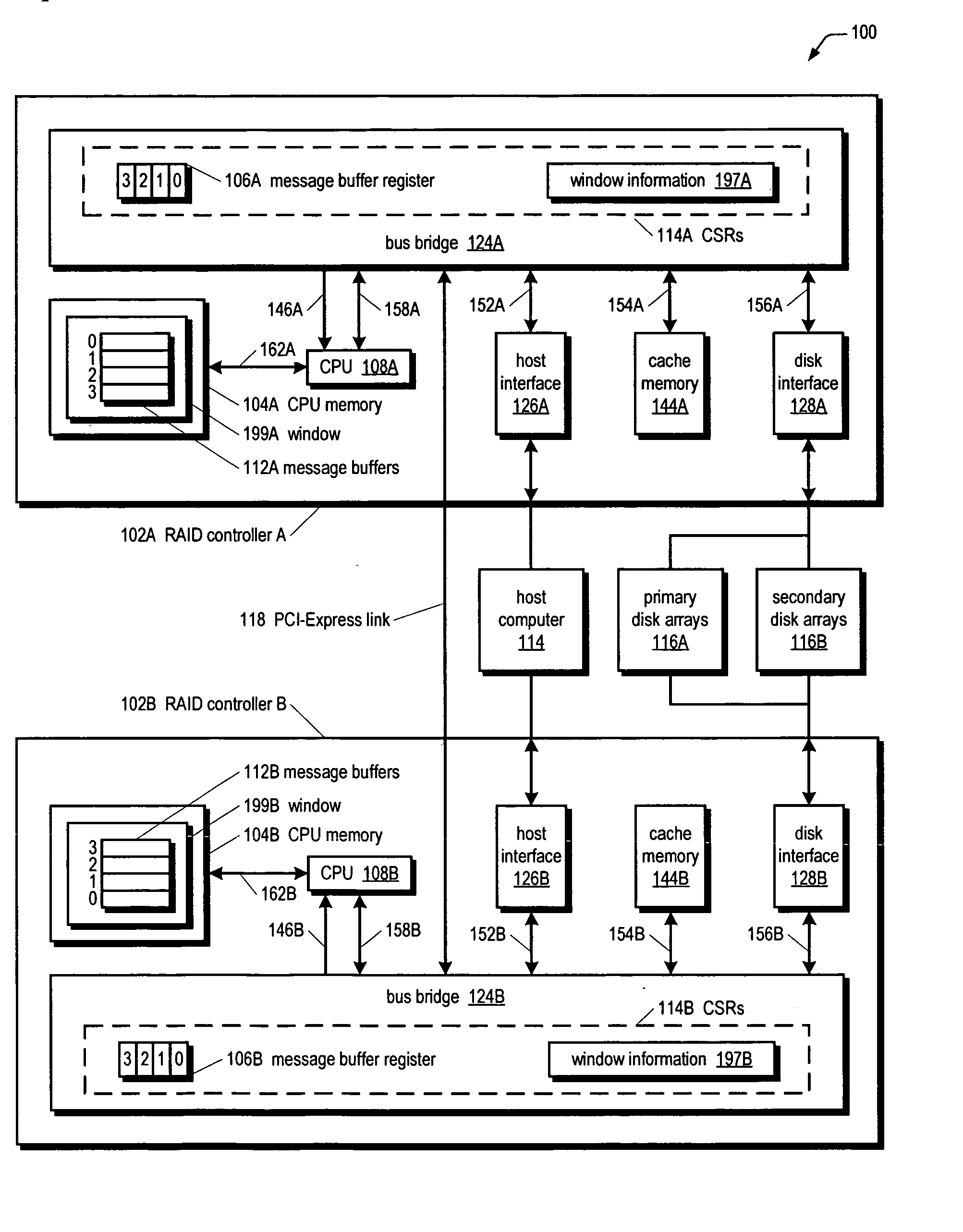
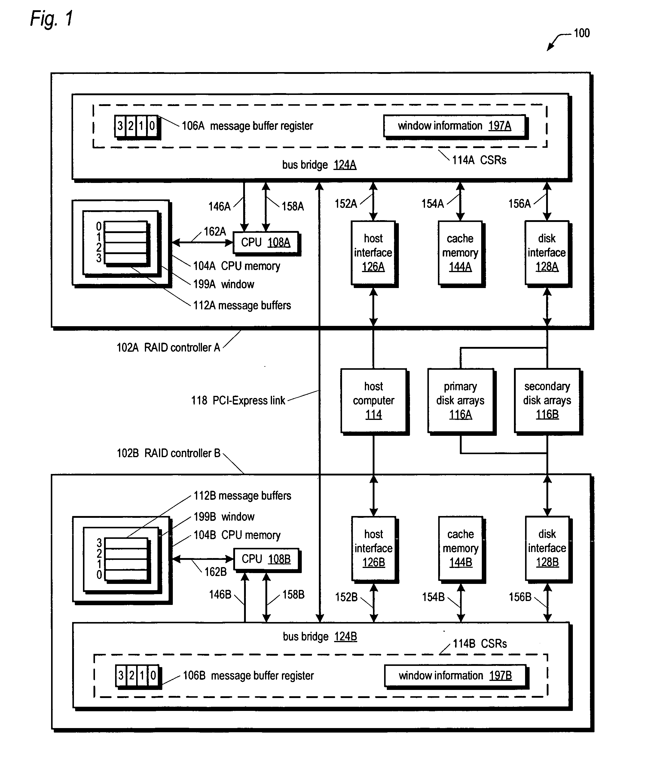
[0031] Referring now to FIG. 1, a block diagram illustrating an active-active redundant fault-tolerant RAID subsystem 100 according to one embodiment of the present invention is shown. The subsystem 100 includes two RAID controllers denoted individually RAID controller A 102A and RAID controller B 102B, generically as RAID controller 102, and collectively as RAID controllers 102. The RAID controllers 102 are coupled to one another by a PCI-Express link 118. In one embodiment, the PCI-Express link 118 comprises signal traces on a backplane or mid-plane of a chassis into which the RAID controllers 102 plug. In one embodiment, the RAID controllers 102 are hot-pluggable into the backplane.

[0032] The PCI-Express link 118 is an efficient high-speed serial link designed to transfer data between components within a computer system as described in the PCI Express Base Specification Revision 1.0a, Apr. 15, 2003. The PCI Express specification is managed and disseminated through the PCI Specia...


PUM


Abstract

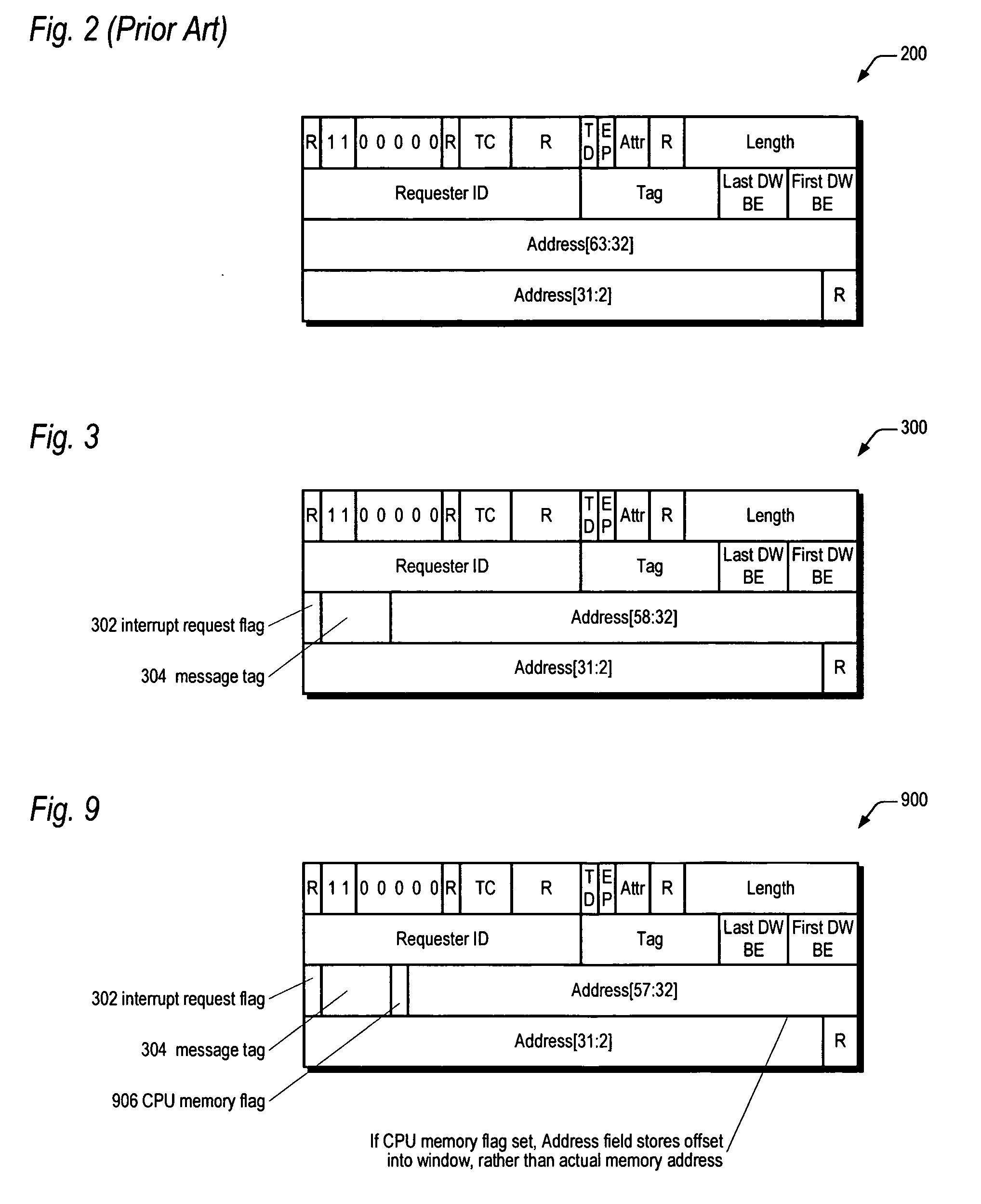
A fault-tolerant mass storage system includes two RAID controllers that communicate via a PCI-Express link. Each controller has a bus bridge coupled to the link, a cache memory that caches user data for storage on disk drives controlled by the controllers, and a CPU. The CPU fetches and executes program instructions from a CPU memory coupled to it. The CPU programs the bus bridge with window information defining a window of locations within the CPU memory, which is less than an entirety of the CPU memory. The bus bridge receives data on the link from the other controller and if the header of a packet containing the data indicates it is destined for the CPU memory, the bus bridge translates the address of the data so as to write the data safely to the CPU memory, but only within the window and nowhere else within the CPU memory.

Description

CROSS REFERENCE TO RELATED APPLICATION(S) [0001] This application is a continuation-in-part (CIP) of the following co-pending Non-Provisional U.S. patent application, which is hereby incorporated by reference in its entirety for all purposes: Serial No.(Docket No.)Filing DateTitle11 / 178,7277 / 11 / 2005RAID SYSTEM FOR PERFORMING(CHAP.0125)EFFICIENT MIRRORED POSTED-WRITE OPERATIONS[0002] Pending U.S. patent application Ser. No. 11 / 178,727 (CHAP.0125) claims the benefit of the following pending U.S. Provisional Application, which is hereby incorporated by reference in its entirety for all purposes: Serial No.(Docket No.)Filing DateTitle60 / 645,3401 / 20 / 2005METHOD FOR EFFICIENT INTER-(CHAP.0125)PROCESSOR COMMUNICATION INAN ACTIVE-ACTIVE RAID SYSTEMUSING PCI-EXPRESS LINKS[0003] This application claims the benefit of the following Provisional U.S. Patent Application, which is hereby incorporated by reference in its entirety for all purposes: Serial No.(Docket No.)Filing DateTitle60 / 694,4426...

Claims


Application Information

Patent Timeline
Patent Type & Authority Applications(United States)
IPC IPC(8): G06F13/24
CPCG06F11/2089G06F13/404
Inventor DAVIES, IAN ROBERT
Owner DOT HILL SYST
Learn More