
Catalyst substrate support

a substrate support and catalyst technology, applied in the direction of physical/chemical process catalysts, lighting and heating apparatus, separation processes, etc., can solve the problems of high cost of catalytic materials in the coating, increased damage, failure due to channel or passage collapse, etc., to reduce creep stresses in the cellular structure and reduce gravitational stresses

Active Publication Date: 2006-07-20
DCL INT
View PDF71 Cites 6 Cited by
  • Summary
  • Abstract
  • Description
  • Claims
  • Application Information

AI Technical Summary

Benefits of technology

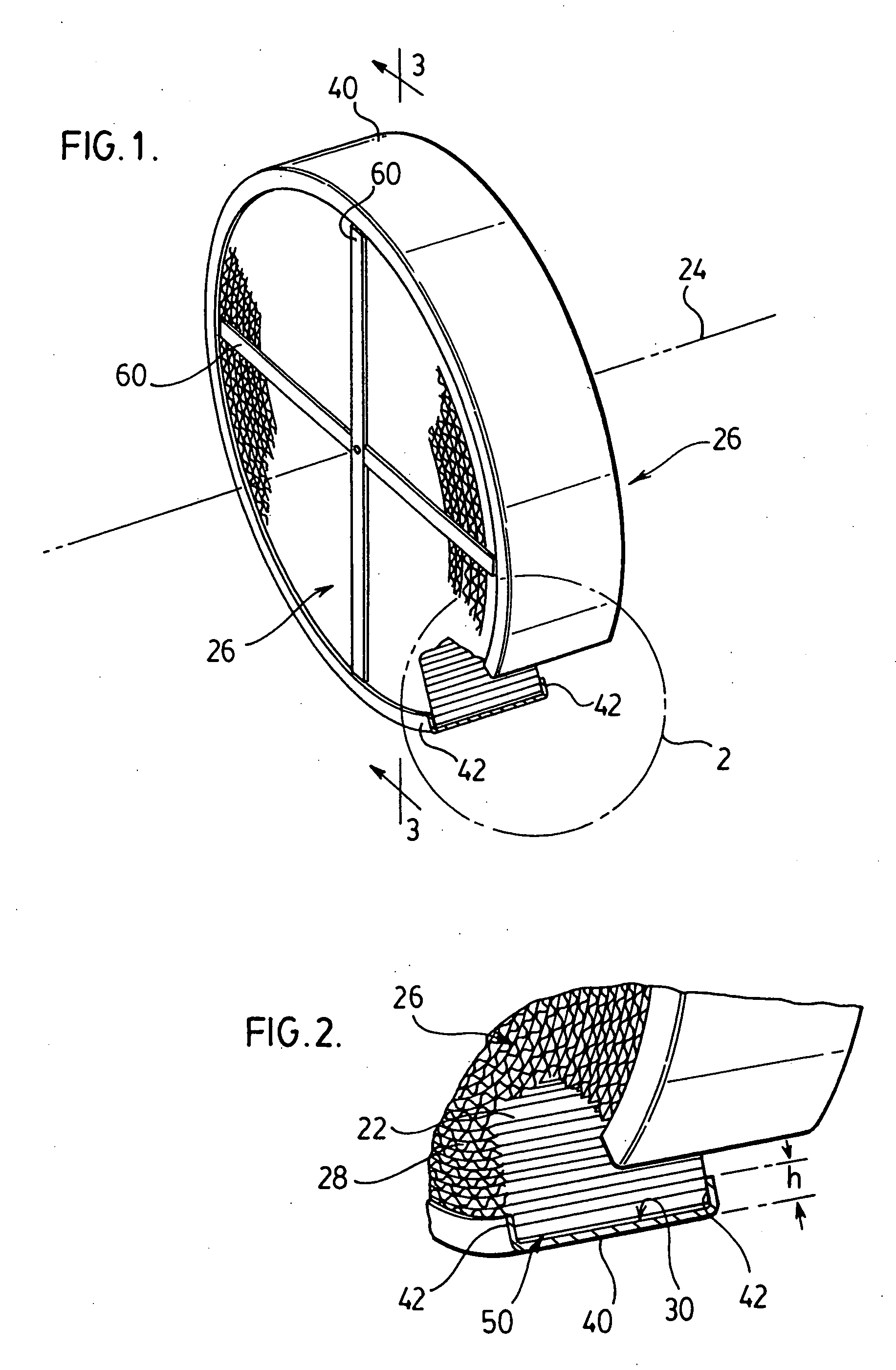
[0009] In general terms, the present invention reduces creep stresses in the cellular structure of the catalyst substrate support by reducing gravitational stresses on the support and by accommodating thermal expansion of the cellular structure.
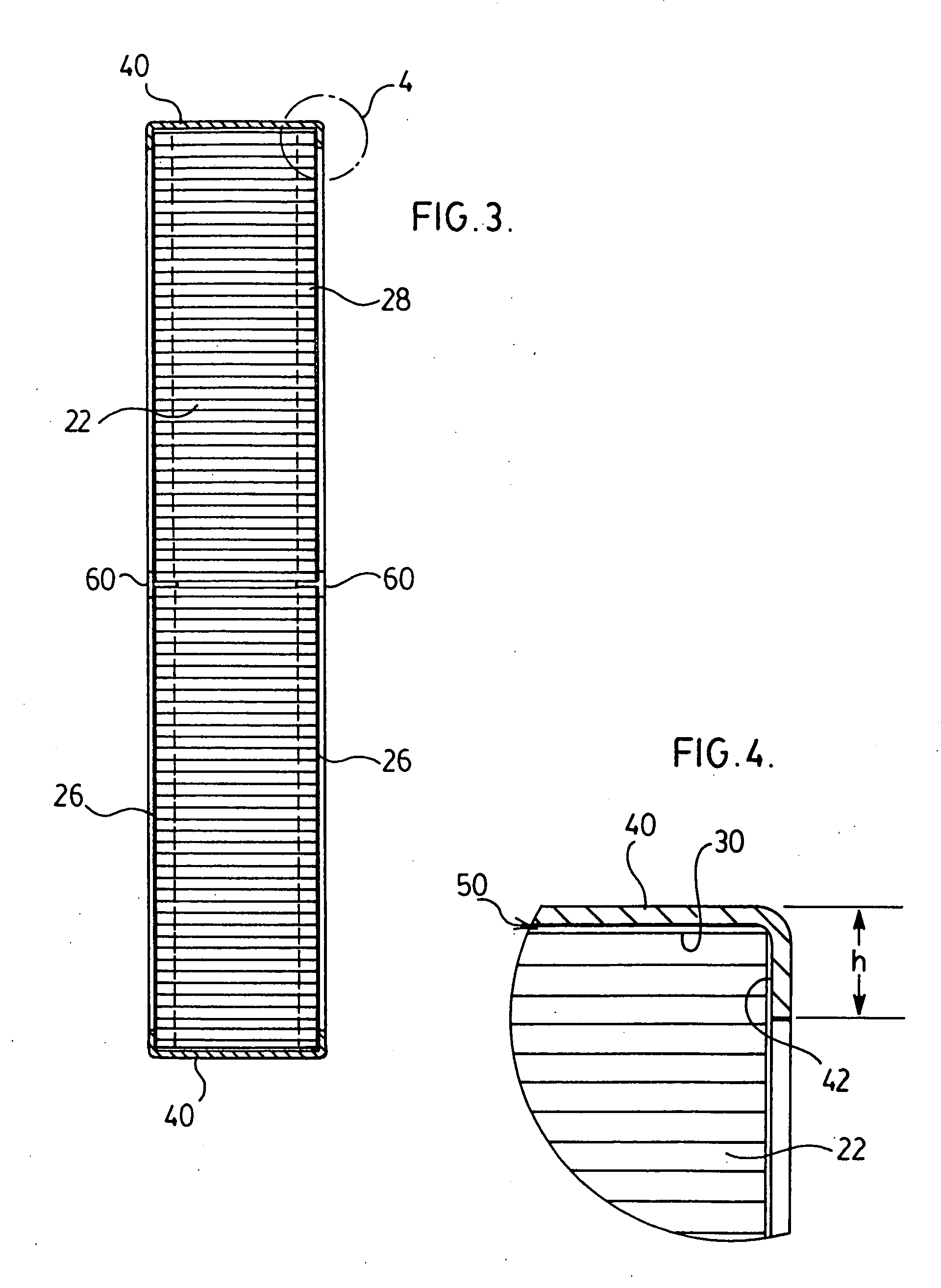
[0010] More specifically, a catalyst substrate support is provided which has a corrugated foil honeycomb matrix having an axis and defining a plurality of passages therethrough which are generally parallel to the axis and extend between opposite end faces of the matrix. A peripheral mantle extends about an outer perimeter of the matrix. The peripheral mantle has inwardly extending flanges which extend across an outer periphery of the opposite end faces to cover outermost of the passages and restrict fluid flow between the peripheral mantle and the matrix.
[0013] The cross members may be slidingly received by the recesses in the matrix to avoid transfer of thermally induced stresses between the matrix and the peripheral mantle.

Problems solved by technology

Industrial applications pose different challenges than automotive applications to the service life of the catalyst substrate.
In larger sized converters, failures due to collapse of the channels or passages arise.
The gas flow leakage in turn causes the matrix to flutter thereby incurring more damage until it becomes ineffective.
In view of the relatively modest size, the individual elements are not designed with weight bearing or thermal expansion considerations in mind.
As the catalytic materials in the coating are very expensive (such as platinum) currently the amount of the coating applied is related to the expected service life of the support structure.
While this would increase the cost of the converter it is believed that any such increase would be outweighed by costs associated with the downtime required to exchange the matrix within the converter or to exchange the entire converter.

Method used


Image

  • Catalyst substrate support
  • Catalyst substrate support
  • Catalyst substrate support

Examples


Embodiment Construction

[0022] A catalyst substrate support according to the present invention is generally indicated by reference 20 in the accompanying illustrations. The catalyst substrate support has a corrugated foil honeycomb matrix 22 having an axis 24. The matrix 22 has opposite end faces 26. The matrix 22 defines passages 28 which extend between the opposite end faces 26 to allow fluid flow (typically gaseous) through the matrix 22. The passages 28 are generally parallel to the axis 24.

[0023] A parallel mantle 40 extends about an outer perimeter 30 of the matrix 22. The peripheral mantle 40 has a pair of inwardly extending flanges 42 which extend across the passages adjacent an outer periphery of the opposite end faces 26. In other words, the matrix 22 is nested in a channel of generally “U” shaped cross-section defined by the flanges 42 and an inner face 44 of the peripheral mantle 40.

[0024] The peripheral mantle 40 may be fabricated by rolling a suitably dimensioned channel and joining its end...


PUM

PropertyMeasurementUnit
Flow rateaaaaaaaaaa
Heightaaaaaaaaaa
Perimeteraaaaaaaaaa

Abstract

A catalyst substrate support is provided which has a corrugated foil honeycomb matrix having an axis and defining a plurality of passages therethrough which are generally parallel to the axis and extend between opposite end faces of the matrix. A peripheral mantle extends about an outer perimeter of the matrix. The peripheral mantle has inwardly extending flanges which extend across an outer periphery of the opposite end faces to cover outermost of the passages and restrict fluid flow between the peripheral mantle and the matrix. The outer perimeter of the matrix and the peripheral mantle may be spaced apart to define a gap for accommodating differential thermal expansions of the matrix and the peripheral mantle, the gap being smaller than a height of the inwardly extending flanges. The catalyst substrate support may have at least one cross member extending across and secured to each of the opposite end faces of the matrix. The matrix may have recesses extending into the opposite end faces for receiving the cross members. The cross members support the matrix in the peripheral mantle to transfer at least part of the gravitational load of the matrix to the mantle. The cross members may be slidingly received by the recesses in the matrix to avoid transfer of thermally induced stresses between the matrix and the peripheral mantle.

Description

FIELD OF THE INVENTION [0001] This invention relates generally to exhaust gas catalytic converters and more particularly to the support of a catalyst substrate in catalytic converters utilizing a corrugated foil matrix catalyst substrate. BACKGROUND OF THE INVENTION [0002] Honeycomb matrixes made from high temperature steel foil are used as support structures for catalytic coatings, for both automotive and industrial (stationary engine) applications. Industrial applications pose different challenges than automotive applications to the service life of the catalyst substrate. This is because of the significantly larger size of industrial type catalytic converters. [0003] The matrix is usually formed by winding previously corrugated foil into a spiral shape to form a multitude of channels or passages. The foil is quite thin, typically on the order of a few thousands of an inch and accordingly relatively easy to bend. In the case of industrial sized units the diameter of the matrix may ...

Claims


Application Information

Patent Timeline
IPC IPC(8): B01J21/04B01J23/02
CPCF01N3/281F01N3/2842F01N2260/10Y10T428/24149F01N2330/02F01N2330/32F01N2450/02F01N2260/18
Inventor MUTER, JOHN P.
Owner DCL INT
Learn More