Image filter, image filtering method and computer program

Inactive Publication Date: 2006-07-20
MEGACHIPS
View PDF10 Cites 4 Cited by
  • Summary
  • Abstract
  • Description
  • Claims
  • Application Information

AI Technical Summary

Benefits of technology

[0014] According to the present invention, the first pixel group containing the pixel of interest, the second pixel group containing the first pixel group, and the third pixel group containing the second pixel group are applied for use in the filtering. The second reference pixel value is calculated based on the third pixel group, and the target set is determined based on the second reference pixel value. This means pixel variations in the wide area in the neighborhood of the pixel of interest can be taken into consideration for defining the target set. The first reference pixel value is calculated based on the first pixel group covering a limited area in the neighborhood of the pixel of interest, and a pixel with a value close to the first reference pixel value is applied for use as a corrective pixel. Thus the corrective pixel can be responsive to local pixel variations around the pixel of interest. Further, the target set is selected from the second pixel group covering an area smaller than that of the third pixel group. Thus the required amount of calculation can be reduced.

Problems solved by technology

However, the mean filter suffers from blurring of high frequency components.
However, the technique introduced in Japanese Patent Application Laid-Open No. 4-235472 fails to perform accurate correction in the event that data error continuously occurs in the neighborhood of a pixel of interest, for example.
Namely, data correction cannot be realized when a median value itself largely deviates from the original pixel value of a pixel of interest.
This technique fails to perform accurate correction, in the event that a distribution of pixel values in a region targeted for the calculation of an average value and a distribution of pixel values of neighboring pixels including a pixel of interest are significantly different from each other, for example.

Method used


Image

  • Image filter, image filtering method and computer program
  • Image filter, image filtering method and computer program
  • Image filter, image filtering method and computer program

Examples


first preferred embodiment

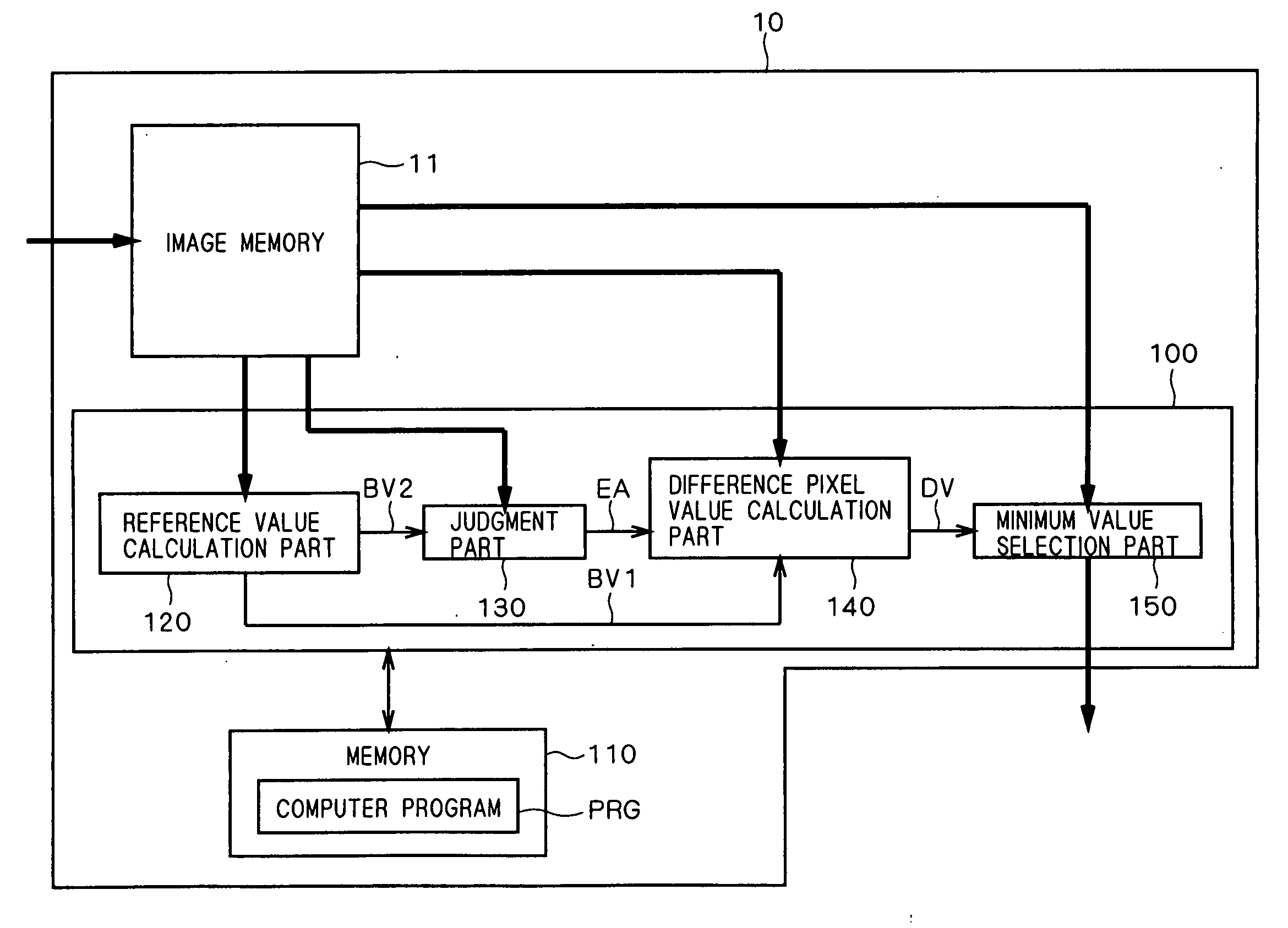
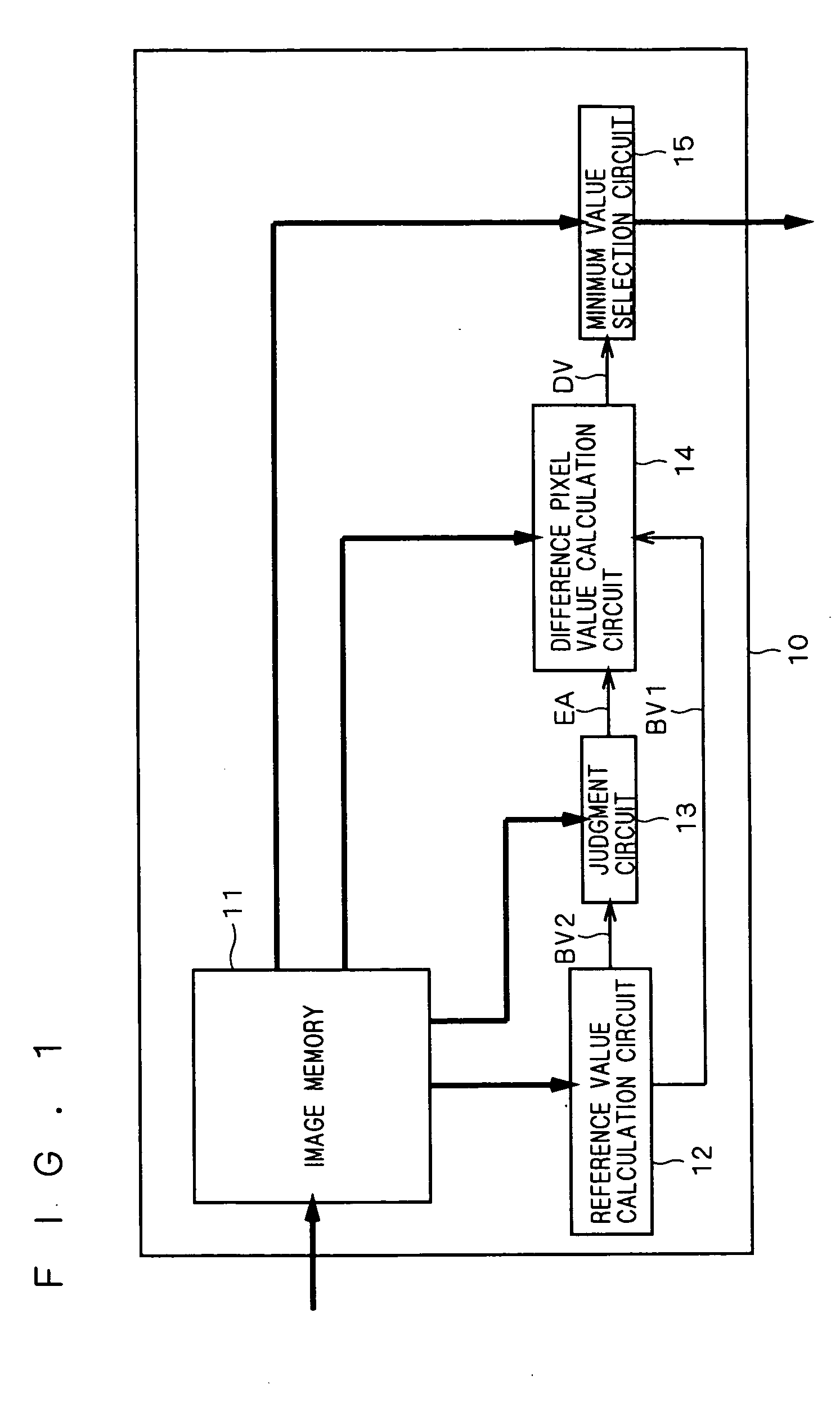
[0025] Preferred embodiments of the present invention will be described with reference to the accompanying drawings. FIG. 1 is a circuit diagram of an image filter 10 according to a first preferred embodiment of the present invention. The image filter 10 comprises an image memory 11, a reference value calculation circuit 12, a judgment circuit 13, a difference pixel value calculation circuit 14 and a minimum value selection circuit 15.

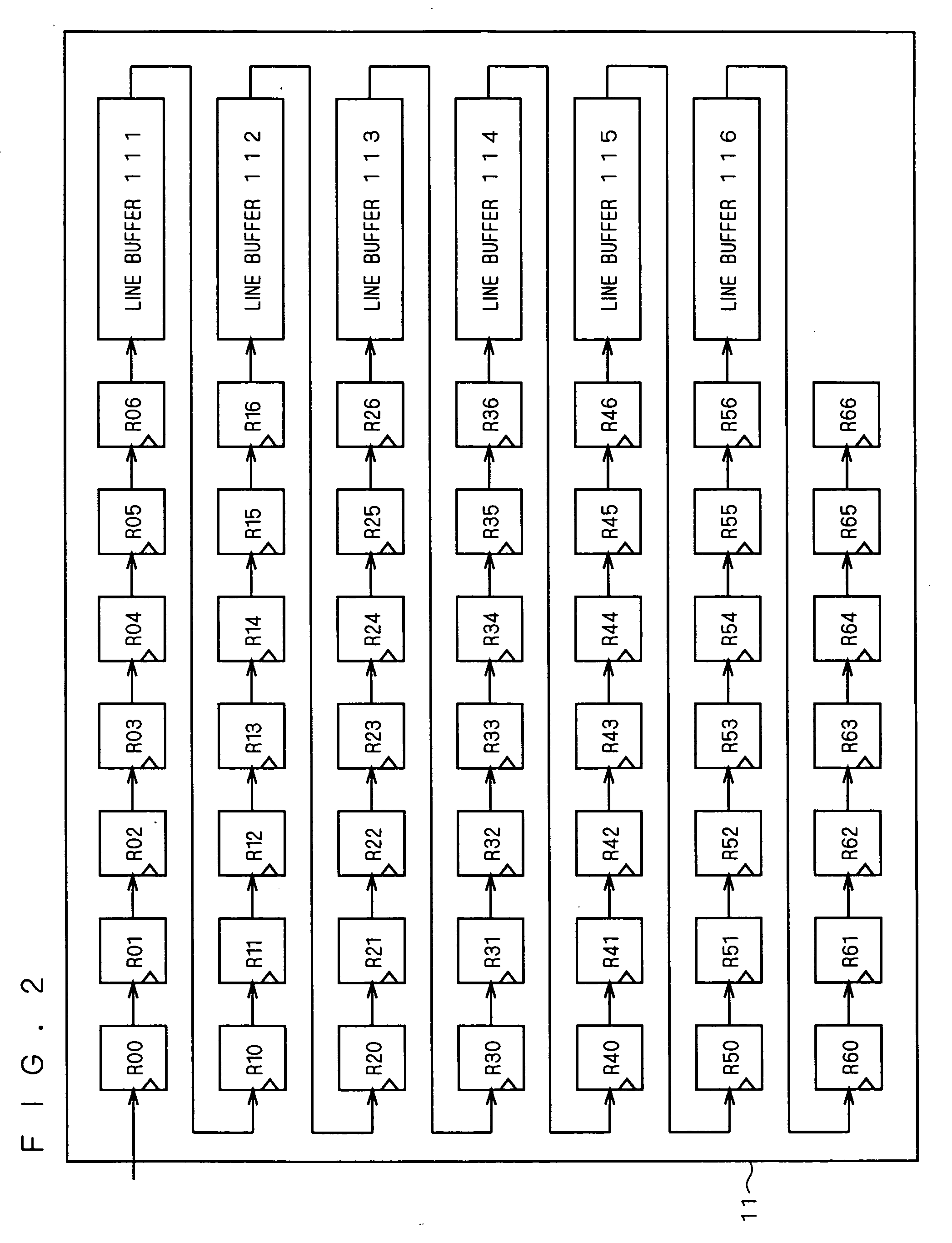
[0026] With reference to FIG. 2, the image memory 11 has 49 registers R00, R01, . . . R66 and six line buffers 111, 112, . . . 116. The 49 registers R00, R01, . . . R66 each have a storage area capable of storing pixel data corresponding to one pixel. Assuming that each horizontal line of image data received by the image filter 10 contains N pixels, the line buffers 111, 112, . . . 116 are FIFO memories each capable of storing pixel data corresponding to (N-7) pixels.

[0027] A more specific configuration will be discussed. In a first line, the registe...

second preferred embodiment

[0049] Next, a second preferred embodiment of the present invention will be described. Like in the first preferred embodiment, pixel data are stored in the image memory 11 and the reference value calculation circuit 12 calculates the first and second reference pixel values BV1 and BV2 in step s1. Then in step s2, the judgment circuit 13 receives the pixel data contained in the second pixel group PA2 from the image memory 11, and divides the second pixel group PA2 into two sub-groups with respect to the second reference pixel value BV2.

[0050] Next, in step s3, the judgment circuit 13 selects one of these two sub-groups containing a larger number of pixels as the target set EA. Namely, of the sub-group of pixels with pixel values greater than the second reference pixel value BV2 and the sub-group of pixels with pixel values smaller than the reference pixel value BV2, the sub-group containing a larger number of pixels is selected as the target set EA.

[0051] The subsequent processes i...

third preferred embodiment

[0055] Next, a third preferred embodiment of the present invention will be described. Like in the first preferred embodiment, pixel data are stored in the image memory 11 and the reference value calculation circuit 12 calculates the first and second reference pixel values BV1 and BV2 in step s1. Then in step s2, the judgment circuit 13 receives the pixel data contained in the second pixel group PA2 from the image memory 11, and divides the second pixel group PA2 into two sub-groups with respect to the second reference pixel value BV2.

[0056] Then in step s3, the judgment circuit 12 selects one of these two sub-groups as the target set EA. That is, the judgment circuit 12 selects either the sub-group containing pixels with pixel values greater than the second reference pixel value BV2 or the sub-group containing pixels with pixel values smaller than the second reference pixel value BV2 as the target set EA. In the sub-group selected as the target set EA, the first reference pixel val...


PUM


Abstract

A first pixel group containing a pixel of interest, a second pixel group containing the first pixel group, and a third pixel group containing the second pixel group are defined. A first reference pixel value is calculated based on the first pixel group, and a second reference pixel value is calculated based on the third pixel group. The second pixel group is divided into two sub-groups with respect to the second reference pixel value. The sub-group containing the pixel of interest is selected as a target set. In the target set, a pixel with a pixel value close to the first reference pixel value is selected as a corrective pixel. The pixel value of the pixel of interest is replaced with the pixel value of the corrective pixel.

Description

BACKGROUND OF THE INVENTION [0001] 1. Field of the Invention [0002] The present invention relates to filtering for reducing noise in images. [0003] 2. Description of the Background Art [0004] A mean filter and a median filter are used to reduce noise in images. The mean filter is used to calculate the average pixel value of a pixel of interest and its neighboring pixels to replace the value of the pixel of interest with this average pixel value. Namely, the intensity of the pixel of interest, or whether the pixel of interest is black or white is determined by the use of the mean filter. The mean filter serves to filter out high frequency components of an image, to thereby realize noise removal and prevention of blurring. [0005] However, the mean filter suffers from blurring of high frequency components. In contrast, a non-linear filter typified by a median filter has received attention by reason of simple algorithm, excellence in edge conservation, no degradation of afterimage in pr...

Claims


Application Information

Patent Timeline
IPC IPC(8): G06K9/40
CPCG06T5/002G06T5/20G06T2207/20012G06T2207/20016G06T2207/20032G06T5/70
Inventor HASEGAWA, HIROMUMORI, MUNEHIROMINAMI, NOBUHIRO
Owner MEGACHIPS
Why Eureka
Try Eureka