
Hearing instrument

a technology for hearing instruments and earpieces, applied in the field of hearing instruments, can solve the problems of limited receiver quality, limited maximum amplification, limited battery life, etc., and achieve the effects of enhancing resistance force, reducing pressure on the skin, and enhancing resistan

Inactive Publication Date: 2006-07-20
SONOVA AG
View PDF16 Cites 172 Cited by
  • Summary
  • Abstract
  • Description
  • Claims
  • Application Information

AI Technical Summary

Benefits of technology

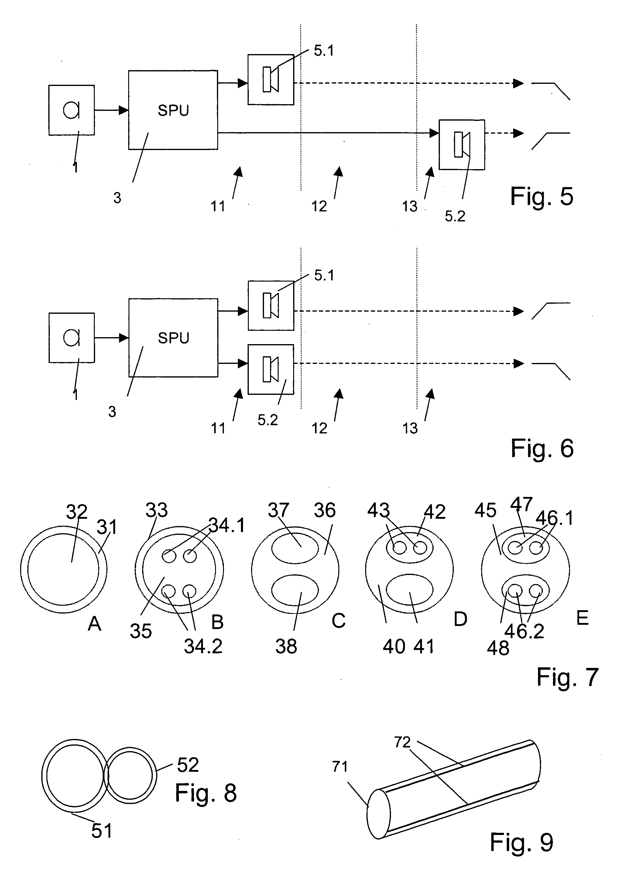
The invention provides a hearing instrument that overcomes the drawbacks of existing hearing instruments, especially in terms of sound quality. The instrument has at least two receivers with different frequency responses, which allows for better overall sound quality and a wider range of frequencies that can be perceived. The receivers can be placed in the ear canal or behind-the-ear, and the instrument can use a single sound conduction channel or multiple channels for sound delivery. The instrument also has a smaller size and reduced power consumption compared to traditional hearing instruments. The invention also provides an external receiver that overcomes previous drawbacks and provides mechanical stability, variability, and does not require an abundance of parts to be delivered with the device.

Problems solved by technology

The sound transmission from the BTE device into the user's ear canal has to be done by a sound conduction tube which modifies the sound impression since the signal transmission characteristic is not homogeneous over the entire frequency range.
However, they have the drawbacks of limited maximum amplification, limited battery lifetime and limited receiver quality, all due to the limited space available.
This plugging of the ear canal may cause undesirable effects, known as occlusion effect which has an impact on the perception of the wearer's own voice and on the wearing comfort.
This hearing aid, however, has the drawback that a special new receiver technology has to be applied (multilayer foil technology) in order to fit the multiple receivers into the ear canal.
This receiver technology has not proven to provide sufficient loudness and sound quality at all relevant frequencies and accordingly has not prevailed on the market.
The acoustical performance is limited by the construction and size of the receiver, making it difficult to provide a high quality sound over a wide frequency range.
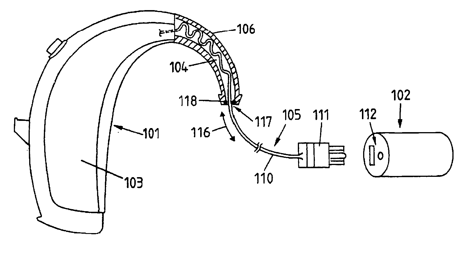
Hearing devices, especially hearing aids, that comprise an external receiver placed outside the device's housing (most often in the ear canal or potentially the concha), have the problem that the connection link between the main component (most often the behind-the-ear component) and the receiver has to be adapted to the particular ear geometry of the wearer.
The disadvantage of such a set-up is that a plurality of interconnection links must be provided to fit the ear geometries.
The disadvantage of the solution proposed by EP 0158391 is that the external receiver assembly is not easily replaceable since the electrical conducting wires are attached to the electronics within the housing in a different way than the connection link.
In addition, EP 0158391 does not reveal a method for securely attaching the connection link to the BTE component.
In fact, an actual realisation of such a device showed severe problems with regard to the mechanical stability.
Careless handling of the device caused a significant stress on the connection link, which may result in wire breaking.
The mechanical reliability of such a solution is unknown.
Also, a faulty length adjustment can not be reversed, since cutting to length is irreversible.
Comfortable fixation of hearing aids that touch the highly sensitive skin in the portion of the ear canal beyond the isthmus (i.e. medial to the isthmus) has always been an issue with deeply fitted hearing instruments.
This is particularly since for this mostly bony section of the ear canal physiological factors related to skin thickness and sensitivity are critical issues.
The development of such solutions was mainly driven by completely-in-the-canal (CIC) related problems in minimizing acoustic feedback due to the dynamics of the ear canal and / or the wish for avoiding to make ear imprints.
Although literature related to deep canal (or peritympanic) devices describes devices that are solely anchored by the seal in the bony part, it is not known how reliable such designs are with regard to unwanted displacements or with regard to comfort.
Deformation of the tip due to the ear canal dimensions will cause the vent cross sections to change unpredictably, such that the acoustic coupling changes correspondingly.
The disadvantage of all universal-fit s receiver or hearing device holder solutions is that the positioning of the receiver within the ear canal is not reproducible.
The resulting uncertainty of positioning and venting causes variations of the acoustic coupling, which limits the acoustic performance of the hearing aid: the hearing aid's gain may not be optimised for the particular geometry the earpiece assumes when inserted in the ear canal.
Further, the assembly is usually not firmly positioned in the ear canal and may walk out and / or may cause a tickling sensation, either during jaw movements or when the assembly is touched from the outside with fingers.
However, such a set-up with a custom shaped CIC component has the disadvantage that the volume between the CIC component and the tympanic membrane is largely closed which reduces the wearing comfort and increases the occlusion effect.
It is not possible to exchange receivers except by replacing the entire CIC component.
However, configurations suffer from the drawback that even if the configuration is an open mold configuration or has a vent, it is may be difficult to provide enough air exchange between an inner portion of the ear canal and the outside.
Also, such state-of-the-art custom shaped earpieces may usually not be made compressible and cause discomfort during jaw movements.

Method used


Image

  • Hearing instrument
  • Hearing instrument
  • Hearing instrument

Examples


first embodiment

[0282] In a first embodiment illustrated in FIG. 29 the fixation means 321 is a hollow reversibly compressible tubular element, for example made of compressible foam. The tube has a length of for example about 15 to 20 mm and is made of biocompatible material. This tube is placed in the ear canal before the receiver component is inserted. The inner radius of the tube is such that when the tube is placed in the bony part of the ear canal, the largest cross-section is smaller than the cross section of the receiver component to be inserted.

[0283] The receiver component has for example an oval shape and a cross-section that is minimized with regard to the cross-section of the ear canal, such that the amount of cerumen that is pushed into the ear canal during insertion is minimized. During insertion the receiver component is guided into the tube with the help of the oval shape of the component and possibly with an increased inner radius at the lateral end of the scaffold. During insertio...

second embodiment

[0288] In preferred realisations of the second embodiment, the holding elements are configured so as to provide an enforced resistance against longitudinal displacement while the radial pressure on the skin is kept minimal. In a first variant, shown in FIG. 31, holding elements 332.1 at or near the tube entrance (i.e. holding elements that are, when the in-the-ear-canal component 302 is inserted, towards on the side of the in-the-ear-canal component 302 towards the ear canal's exit, are stronger. This will somewhat enhance the forces during introduction of the in-the-ear-canal component 302, but provides mechanical stability against unwanted removal of the in-the-ear-canal component 302 without any additional force upon the ear canal skin, while the receiver 304 is in its intended position. The holding elements at the fixation means' end may also be stronger than the holding elements in a middle region so as to provide some resistance against an introduction of the in-the-ear-canal ...


PUM


Abstract

According to the first aspect of the invention, a hearing instrument with at least one microphone and signal processing comprises at least two receivers having a different frequency response. At least a first one of the receivers is placed outside the ear canal, for example in a behind-the-ear component. According to the second aspect of the invention, a hearing instrument comprising a behind-the-ear component and an external component for being placed in the user's ear canal or in the user's ear as well as a connection link between the behind-the-ear component and the external component is provided, where the connection link is reversibly pluggable to the behind-the-ear component and / or the in-the-ear-canal component and has a length that is reversibly adjustable. The hearing instrument also comprises fixation means for reversibly fixing the adjusted length of the connection link. A hearing instrument according to the third aspect comprises a fixation means separate from the in-the-ear-canal component. The fixation means may be positioned in the ear canal and rest therein. The in-the-ear-canal component may be connected to the fixation means and detached therefrom when the same is already in the ear canal. A hearing instrument according to the fourth aspect of the invention comprises an in-the-ear-canal component to be placed in a user's ear canal and fixation means for fixing it in the ear canal. The fixation means comprise an outer shell which is shaped to fit (i.e. custom shaped to fit the specific user's ear geometry) in the user's ear canal and a mounting structure for holding the in-the-ear-canal component. The outer shell is preferably resilient, i.e. has an elasticity allowing temporal deformation.

Description

FIELD OF THE INVENTION [0001] The invention relates to hearing instruments, in particular hearing aids. BACKGROUND OF THE INVENTION [0002] State of the art hearing instruments are usually either behind-the-ear (BTE) hearing devices, in-the-ear (ITE) hearing devices, in-the-canal (ITC) hearing devices or completely-in-the-canal (CIC) hearing devices. BTE hearing devices offer, due to the available space and the resulting possibility to use receivers of larger dimensions, and the opportunity to provide a rather high amplification and to obtain a usually satisfying sound quality. The sound transmission from the BTE device into the user's ear canal has to be done by a sound conduction tube which modifies the sound impression since the signal transmission characteristic is not homogeneous over the entire frequency range. Some of these modifications are wanted, others are unwanted and, if possible, are eliminated by means of acoustic filters in the sound conduction tube. ITE, ITC and CIC ...

Claims


Application Information

Patent Timeline
Patent Type & Authority Applications(United States)
IPC IPC(8): H04R25/00
CPCH04R1/1058H04R25/48H04R25/60H04R25/652H04R2460/11H04R2460/17H04R25/604H04R25/658H04R1/24B33Y80/00B33Y50/00H04R2225/57H04R25/607H04R25/609H04R25/603
Inventor VON DOMBROWSKI, SVENLEYSIEFFER, HANSGABATHULER, BRUNO
Owner SONOVA AG
Learn More